Main frame
Drill holes in 900 mm profiles
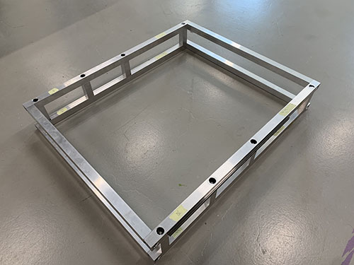
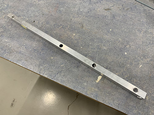
The main frame consists of two separate frames, the lower and the upper frame. The two frames are kept together using threaded rods, washers and nuts. To enable the threaded rods to slide through the aluminium profiles, holes needed to be drilled.
First, a sharpie was used to indicate where all the holes were going in the 900mm profiles (O07). This was done by using a set square and a penn. A bradawl and a hammer were then used to make indentations at the center of the holes.
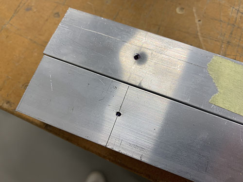
A 9 mm drill-bit and a bench drill was used to drill the holes straight through the profiles.
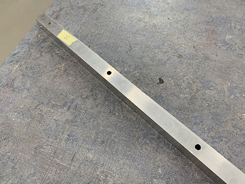
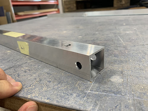
To be able to access the nuts and tight them with a socket wrench, some holes (facing outwards, see Fusion360 CAD file) needed to be enlarged. A sharpie was used to mark all the holes that needed to be enlarged.
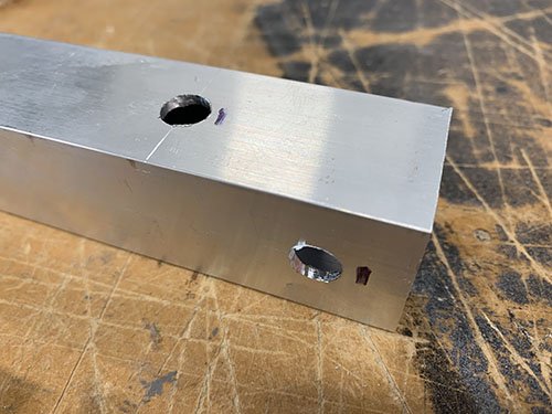
A step drill was then used to enlarge the holes holes to 20 mm. A tip is to measure the size of your socket wrench and keep the holes as small as possible, while you're still able to tighten the nuts. To be able to see which step you're aiming for on the step drill, attach a small piece of masking tape on the step above.
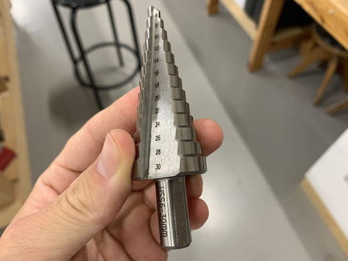
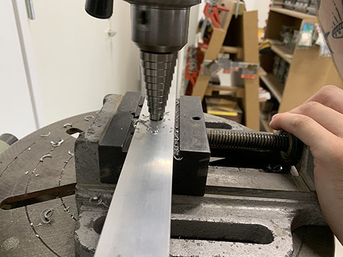
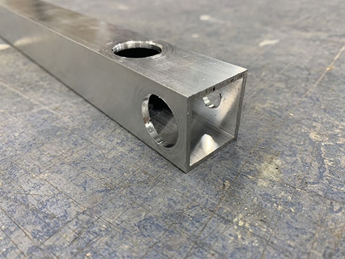
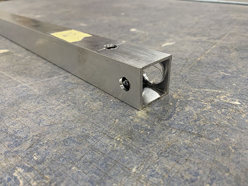
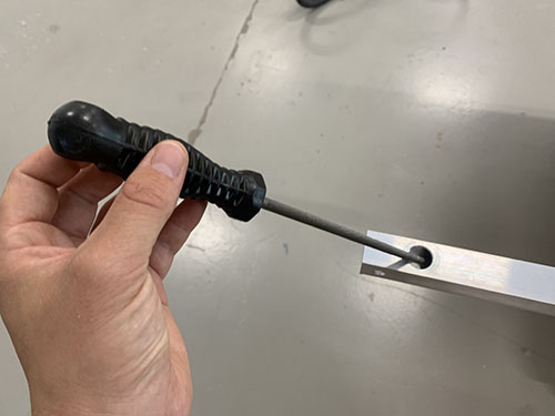
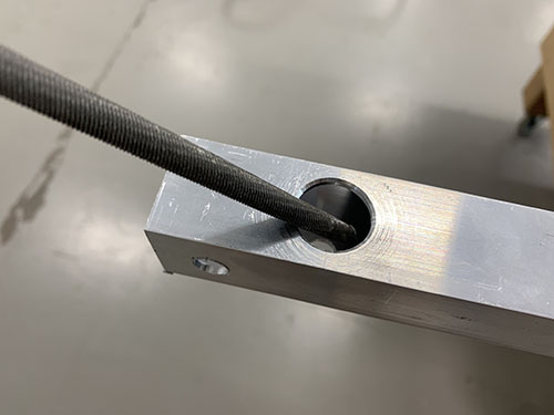
The edges were finally smoothed out using a round metal file.
Rails to 900 mm profiles
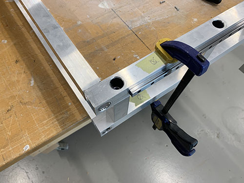
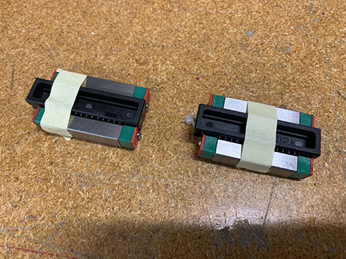
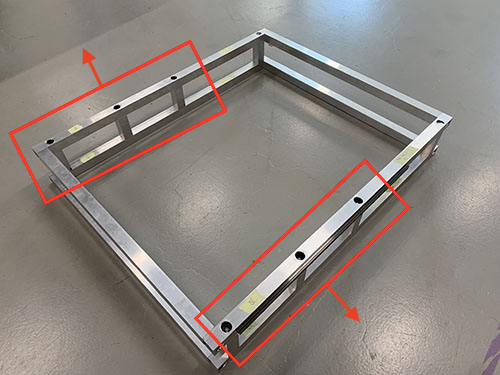
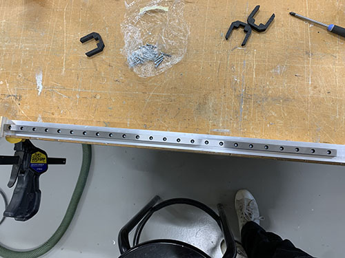
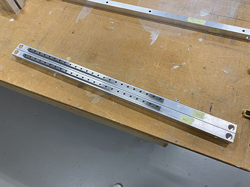
Before the upper and lower frames were assembled, two 600 mm MGN12H rails (O21) were attached to the 900 mm aluminium profiles (O07) of the upper frame. They were attached to the sides facing outwards and above the three 80 mm vertical beams (connecting the lower and upper frame). A tip is to place all the profiles as they should go to make sure that you're attaching the rails to the correct faces (see the red boxes on the image below). Also, be very careful when removing the MGN12H blocks (O22) from the rails.
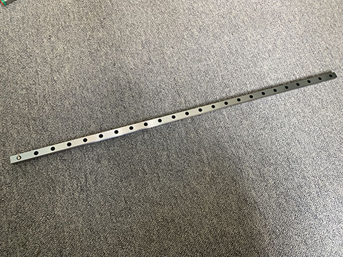
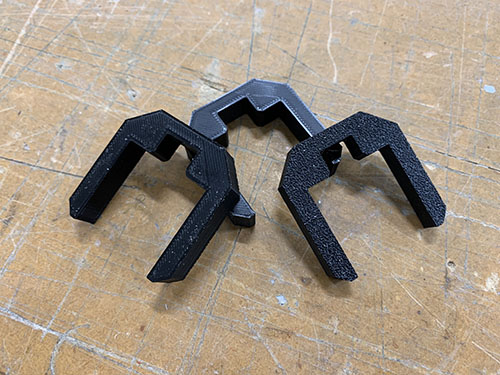
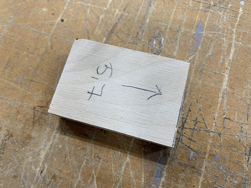
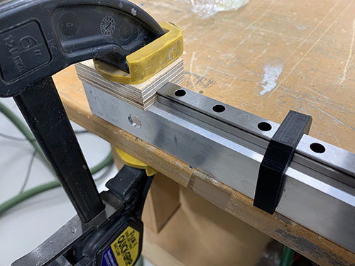
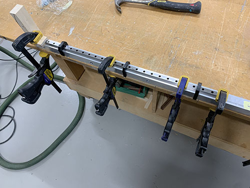
3x 3d-printed support tools (P25) were used to center the rails on the profiles. A 57 mm wood block were cut out and used to attach the rails at the same distance from the end of the profiles on both sides. The rails were then clamped to the profiles.
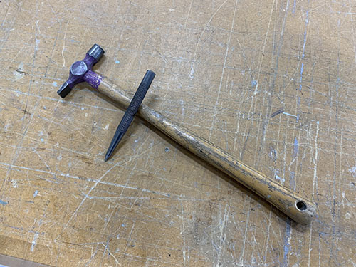
A bradawl and a hammer were then used to make indentations at the center of the holes. Cutting fluid was applied and a 2 mm drill was used to drill all the holes.
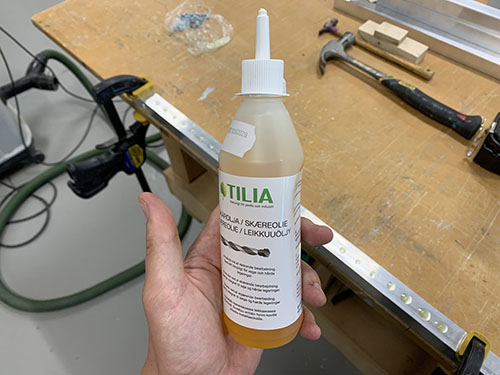
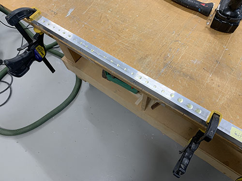
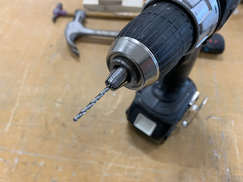
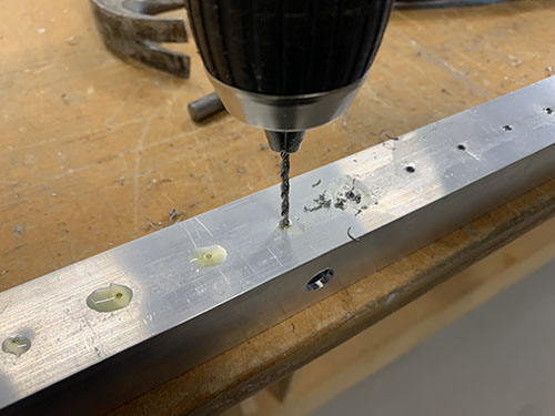
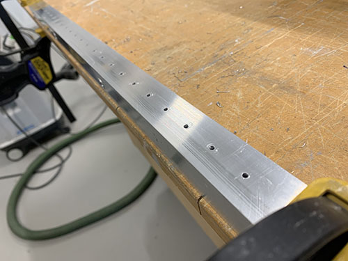
Cutting fluid was then applied once more on the drilled holes and a M3 drill tap was used to create threads in the holes.
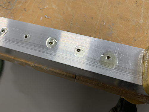
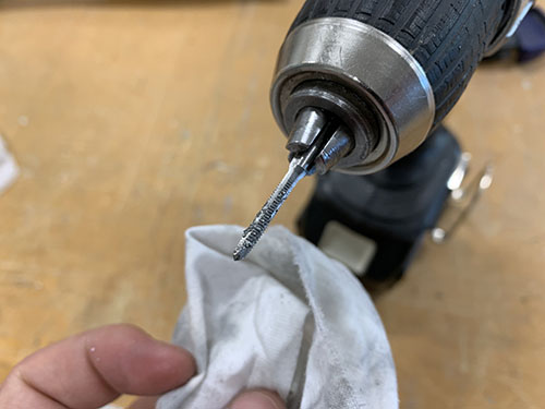
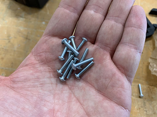
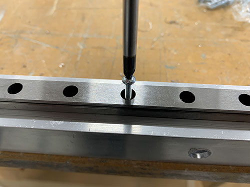
Finally, the rails were attached using 48x 16 mm M3 screws (S03).
Assemble upper and lower frames
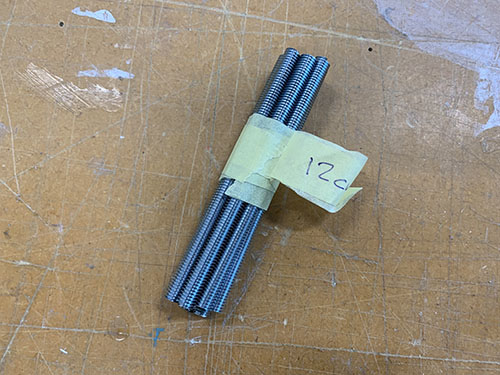
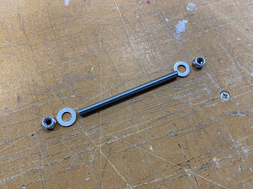
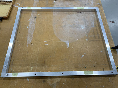
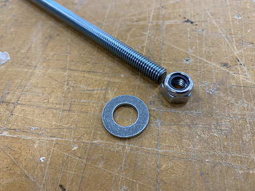
The two frames were assembled using the 4x 717 mm M8 threaded rods (T03), 8x (20mm, 10mm, 2mm) washers (W04) and 8x M8 lock nuts (N03).
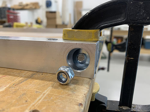
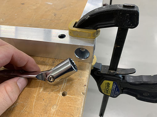
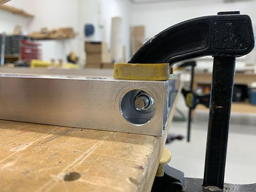
The profiles were first placed in their correct place and clamps were used to keep the profiles aligned. I used two jointed spanners (one one each side) to lock everything in place, but you can also use two socket wrenches. Just make sure that the bits fit into the drilled holes.
Interlock upper and lower frames
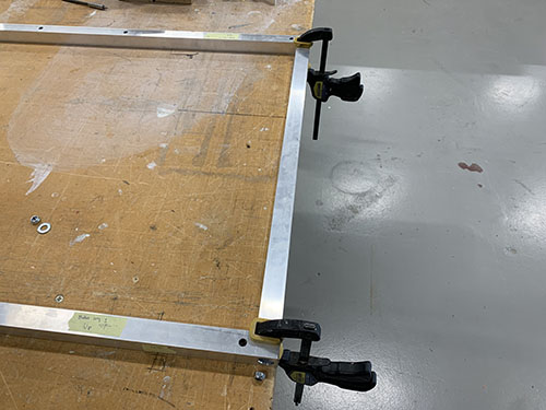
The upper and lower frames and the 8x 80 mm vertical aluminium beams (O06) were first layed out in their correct place. The 803 mm horizontal bridge beams (used later in the tutorial) (O05) and clamps were then used to align the frames on top of each other.
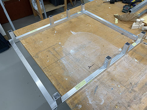
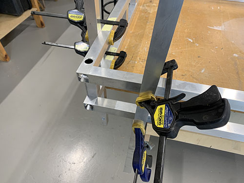
8x 120 mm M8 threaded rods (T02), 16x (20mm, 10mm, 2mm) washers (W04) and 16x M8 lock nuts (N03) were then used to interlock the upper and lower frames, with the 80 mm vertical aluminium profiles in between.