Stepper motors and end-stops
Extend stepper motor wires
All 4 stepper motors (2x Y-axis, 1x X-axis and 1x Z-axis) get their power and movement instructions from the Arduino + CNC shield that in a later step will be attached in the small electronic box. Therefore, the stepper motor cables needed to be extended to reach through the cable chains all the way to the front of the machine, where the small electronic box will be located.
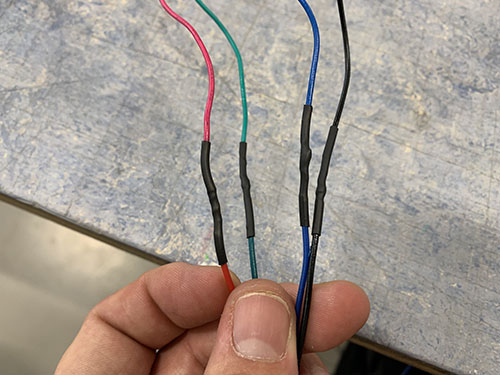
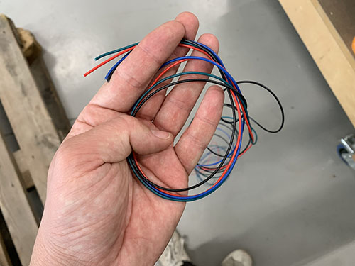
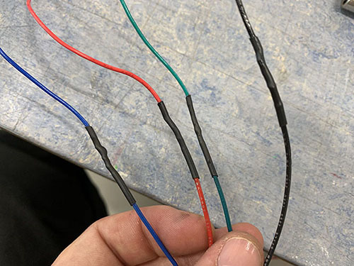
AWG22 cables (E08) of matching colors were used when increasing the length of the stepper motor cables. The same process was used for all the motors:
- The amount of wires needed to reach all the way to the electronic box was approximated and cut. Make sure to have an extra ~300 mm wire from the point where the wires exits the Y-axis cable chain, as this will be needed to reach the small electronic box.
- The ends of the original stepper wires and the extra AWG22 wires were stripped using a wire stripper.
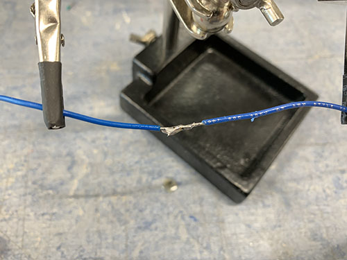
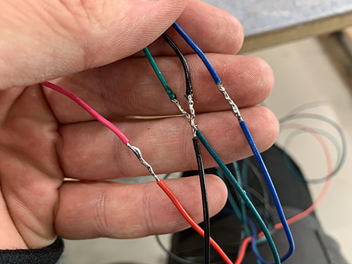
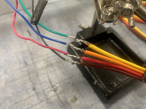
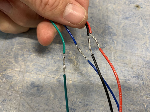
- The colors of the original stepper wires and the extra AWG22 wires were matched up and the stripped ends of the wires were twisted around each other.
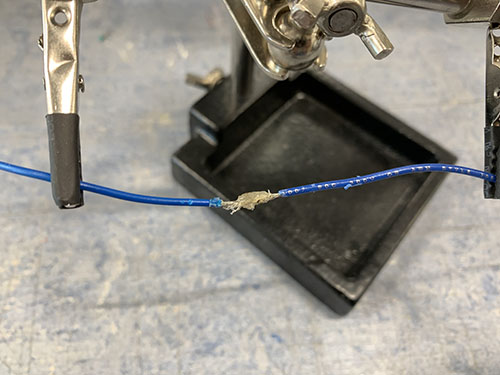
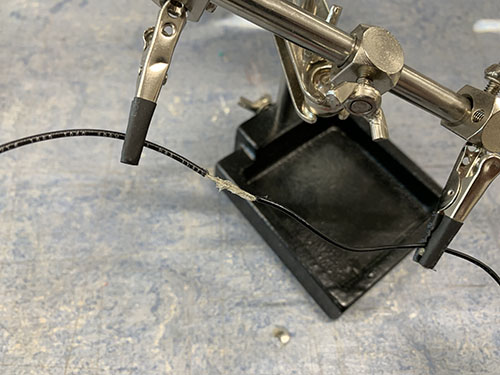
- The twisted wires where then locked in a steady position by a "third hand".
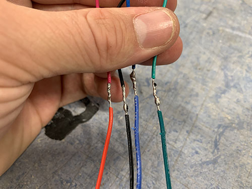
- Soldering grease was applied to the twisted wires and the wires were soldered together.
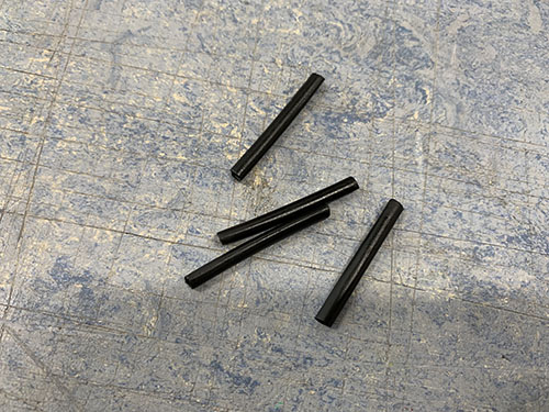
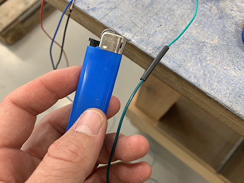
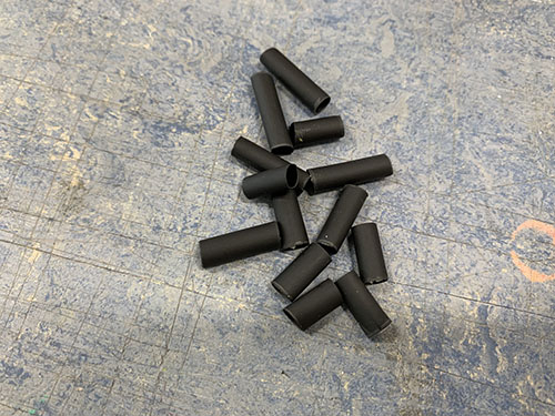
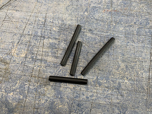
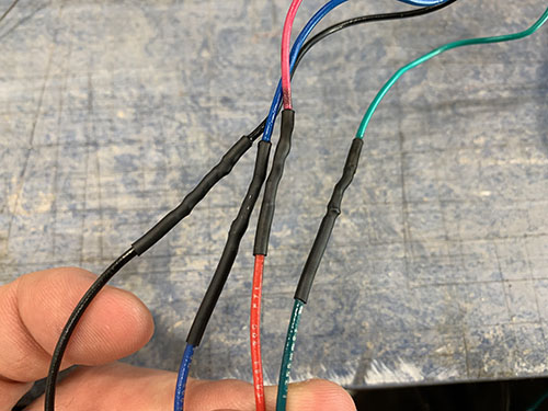
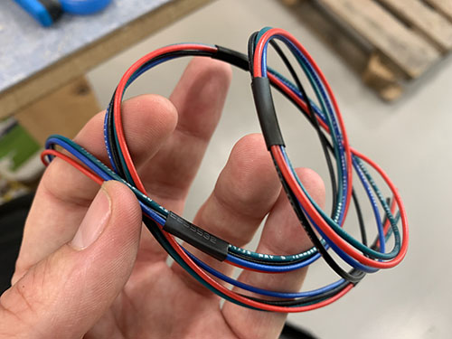
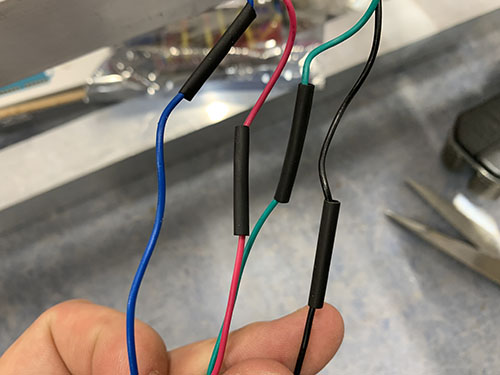
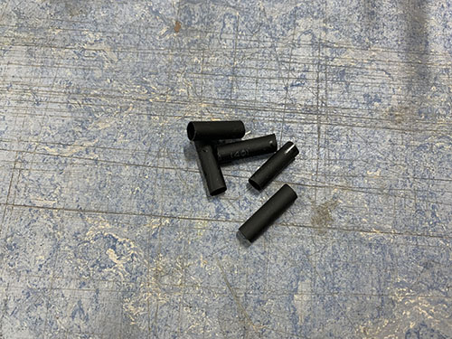
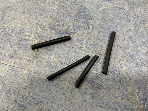
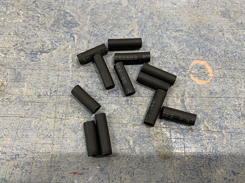
- 4 shrinking tubes (one per cable) were shrunk around the now soldered twisted wires, covering the soldering.
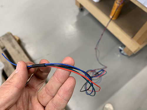
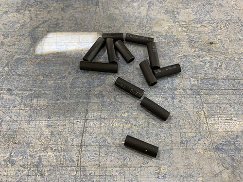
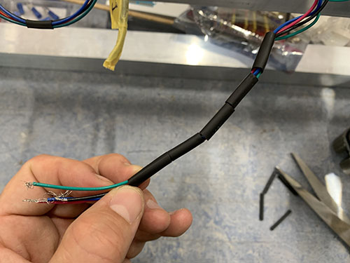
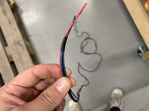
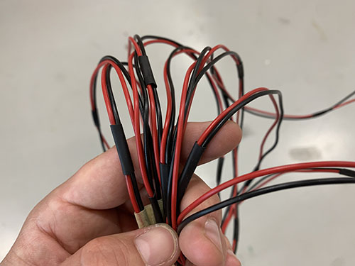
- A handful of larger shrinking tubes were shrunk around all 4 wires to keep them together.
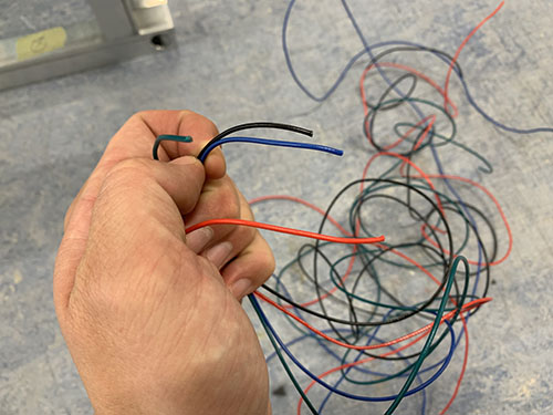
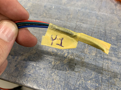
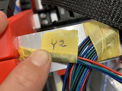
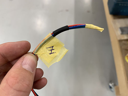
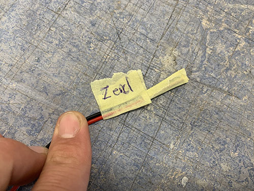
- Finally, the wires were marked using tape and a penn, indicating which stepper motor the wires belonged to. This is important as it will help a lot later on, when the stepper motors are connected to the Arduino.
Y-axis 1
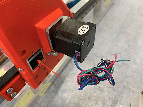
The extended wires of the first Y-axis stepper motor were cut at a length so that they reached through the lower front bridge beam (see red arrow on the next image) and through the Y-axis cable chain going to the front of the CNC machine.
Y-axis 2
The extended wires of the second Y-axis stepper motor were cut at a length so that they reached through the Y-axis cable chain going to the front of the CNC machine.
X-axis
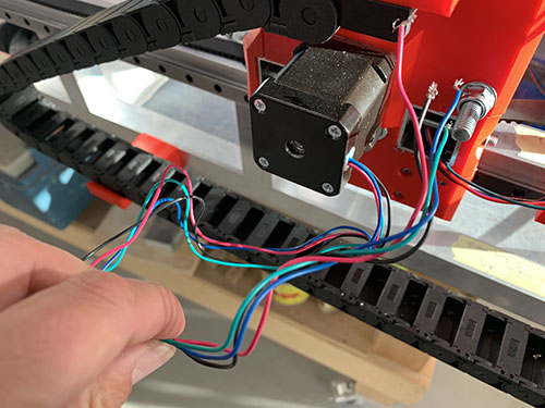
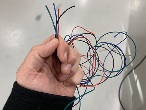
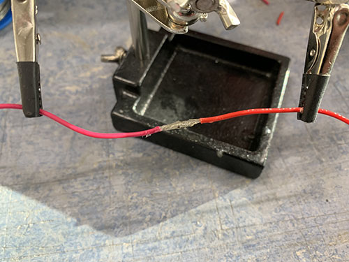
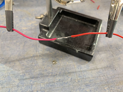
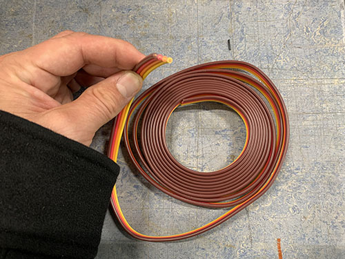
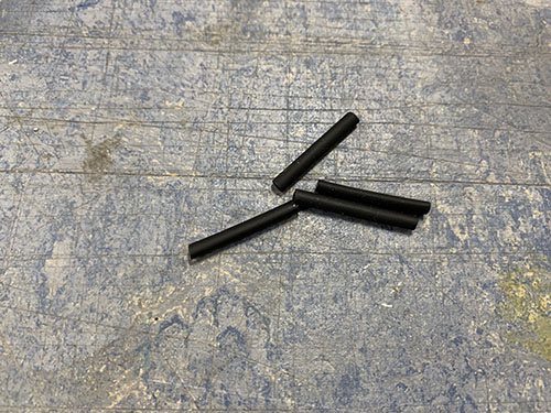
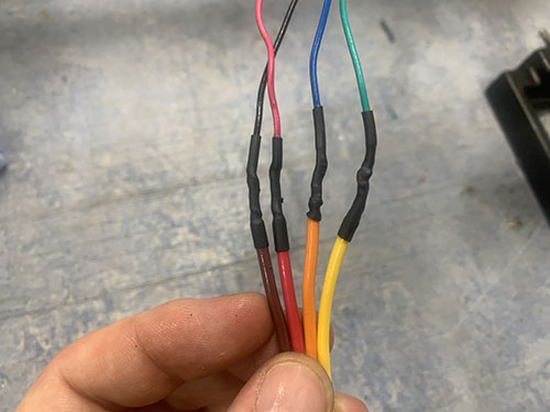
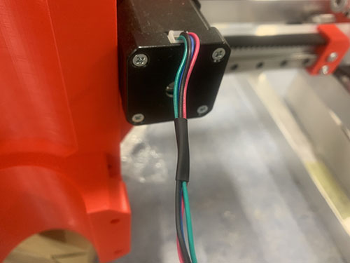
I ran out of AWG22 wires when soldering the X-axis stepper motor cables, therefore you will see different type of cables in the upcoming images. Because of this, I had to insert the shrinking tubes before I soldered the cables. Please disregard this and follow the previous instructions.
The extended wire of the X-axis stepper motor were cut at a length so that they reached up and behind the Z-axis stepper motor, through the X-axis cable chain and through the Y-axis cable chain to the front of the CNC machine.
Z-axis
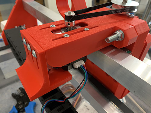
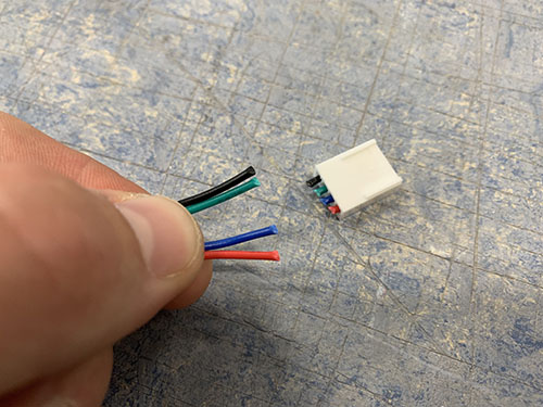
The non-geared NEMA17 motor used for the Z-axis had removable wires, in contrast to the 1:19 geared NEMA17 motors that had non-removable wires. The first step was therefore to connect the wires to the NEMA17 motor and cut of the connector on the other side using a scissor. Otherwise, the same procedure was followed as for the other motors.
The extended wires of the Z-axis stepper motor were cut at a length so that they reached through the X-axis cable chain and through the Y-axis cable chain to the front of the CNC machine.
End-stops and end-stop wires
End-stops are important, as they do not only enable you to home the CNC machine, but they also limit the CNC machine from moving past what is physically possible. When the end-stops are triggered, an alarm is fired and the machine automatically stops.
The wires used for end-stops were 0.75 mm^2 (E03).
X-axis (max)
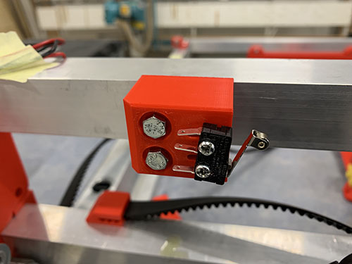
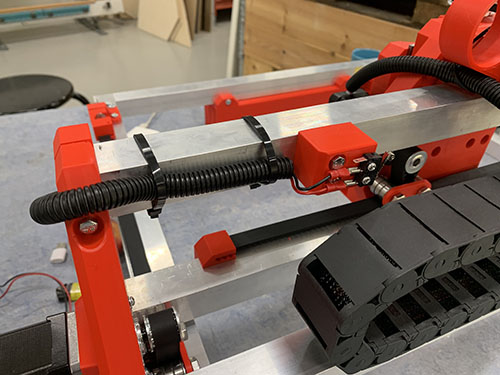
A microswitch (E21) was attached to the thick X-axis (+) end-stop mount (P10) using 2x 12mm M3 screws (S02).
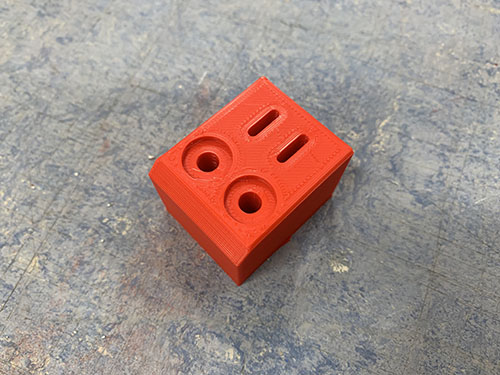
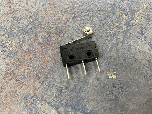
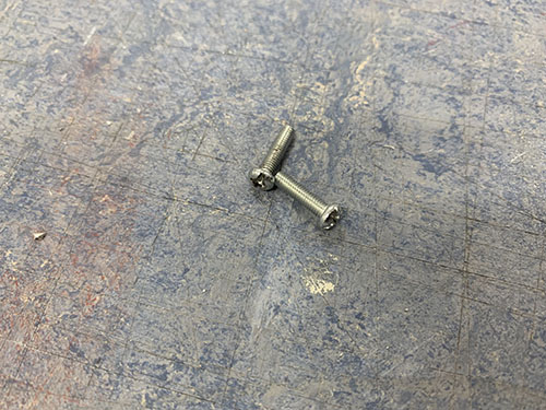
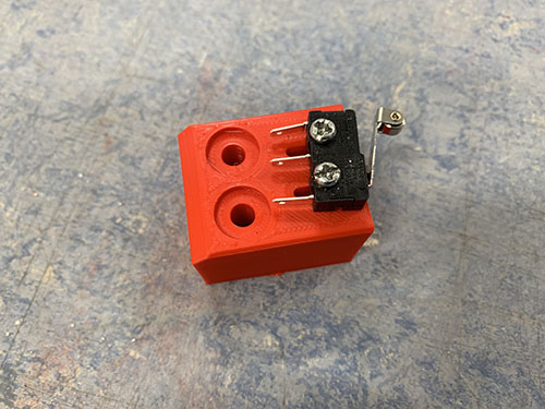
The end-stop mount was then pushed against the backside of the top bridge beam, which enabled the end-stop to trigger on the Z-axis stepper motor. The X-axis (carriage) was then moved to its maximum position and the end-stop mount was positioned in a way so that the end-stop triggered just before the X-axis reached its maximum position.
Please ignore the flexible conduit/hose in the next two images, it will be added in an upcoming step.
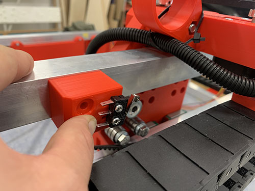
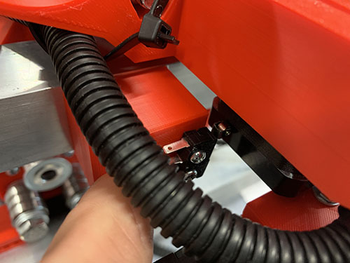
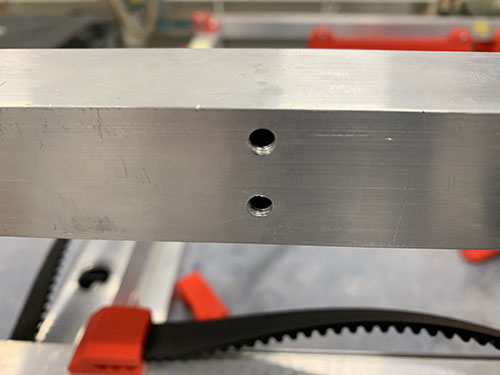
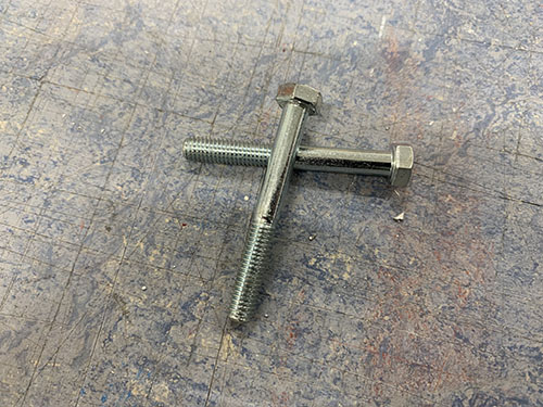
The end-stop mount was then clamped to the upper bridge beam and a small drill (-2 mm) was used to carefully make indentations at the center of the holes. The end-stop mount was then removed. Cutting fluid was applied and a 4 mm drill was used to drill the holes, followed by a M5 drill tap. The end-stop mount was then attached to the upper bridge beam using 2x 40 mm M5 screws (S13).
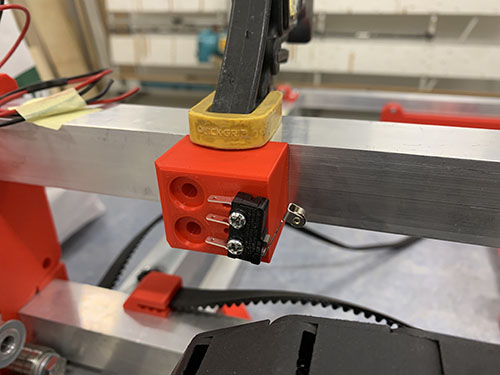
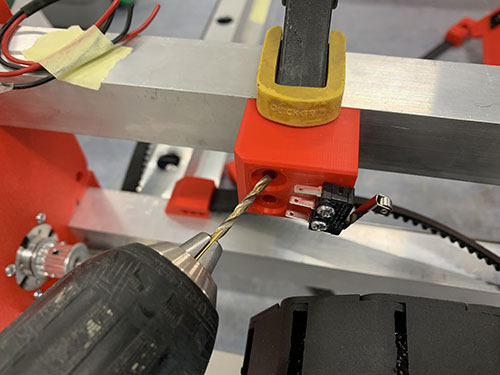
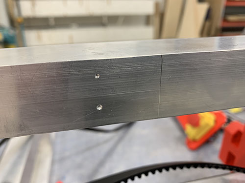
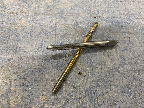
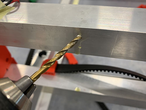
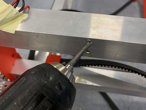
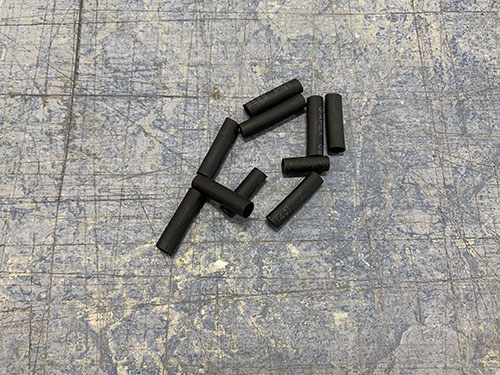
One black and one red 0.75 mm^2 wire (E03) were cut out at a length so that they reached from the X-axis max end-stop to the right side plate, through the top bridge beam and through the Y-axis cable chain to the front of the CNC machine. A handful of shrinking tubes (O24) were shrunk around the wires to keep them together.
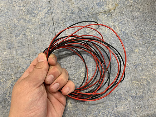
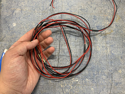
One end of the wires were taped together and inserted through the upper bridge beam to the side plate on the other side.
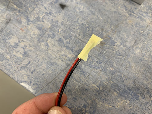
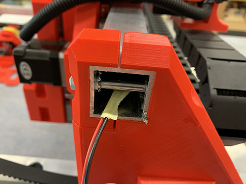
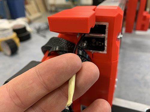
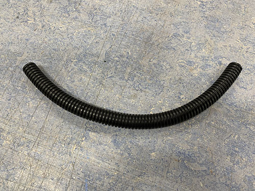
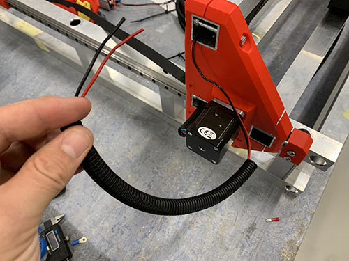
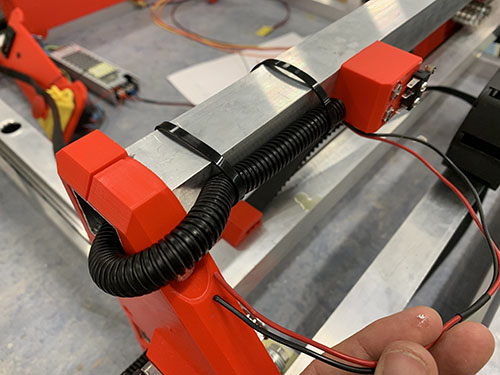
A flexible conduit/hose (O13) was then cut out and the other side of the cables were inserted through the conduit. The flexible conduit was then inserted ~50 mm into the upper bridge beam and the other side was attached to the outside of the upper bridge beam using cable ties (O11).
The end of the wires were stripped and twisted. Two 2.8 mm spade connectors (E25) were then attached to the stripped wires using a plier. The red wire was then attached to C (Common terminal) pinout on the end-stop and the black cable was connected to the NO (Normally Open) pinout.
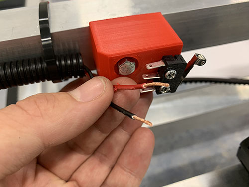
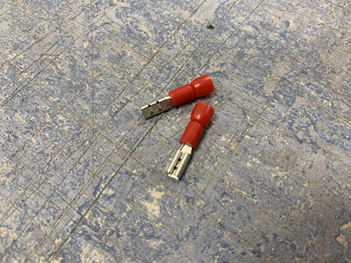
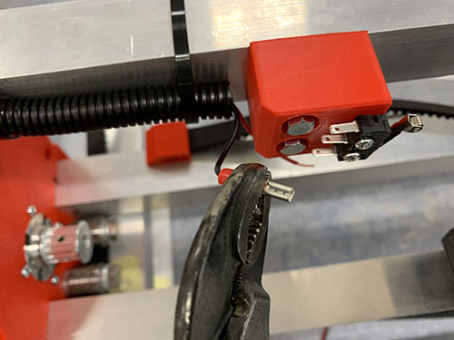
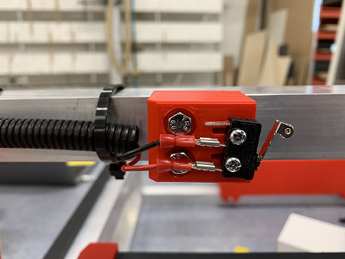
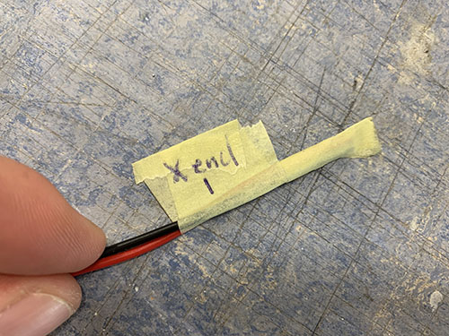
Finally, the open end of the wires were marked using tape (O23) and a penn, indicating which end-stop the cables belonged to. This is important as it will help a lot later on, when the end-stops are connected to the Arduino.
X-axis (min)
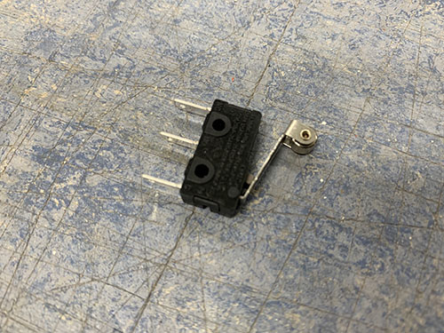
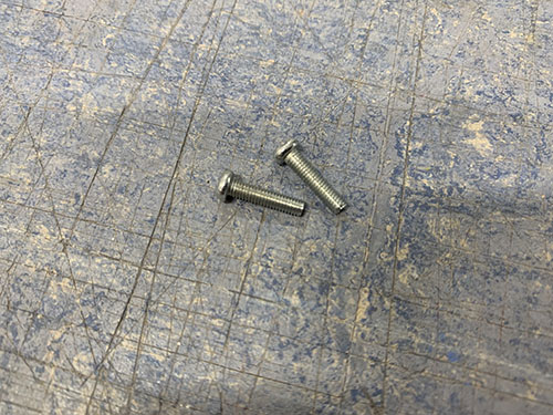
A microswitch (E21) was attached to the X-axis end-stop (-) mount (P08) using 2x 12mm M3 screws (S02).
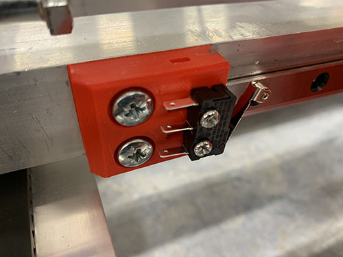
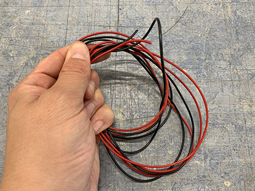
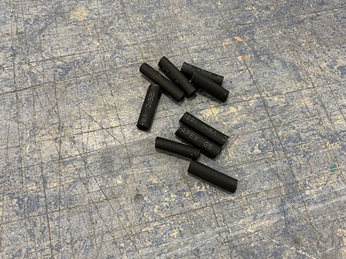
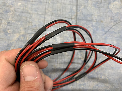
One black and one red 0.75 mm^2 wire (E03) were cut out at a length so that they reached from the X-axis end-stop (-), around the left side plate, through the Y-axis cable chain to the front of the CNC machine. A handful of shrinking tubes (O24) were shrunk around the wires to keep them together.
The end of the wires were stripped and twisted. Two 2.8 mm spade connectors (E25) were then attached to the stripped wires using a plier. The red wire was then attached to C (Common terminal) pinout on the end-stop and the black cable was connected to the NO (Normally Open) pinout.
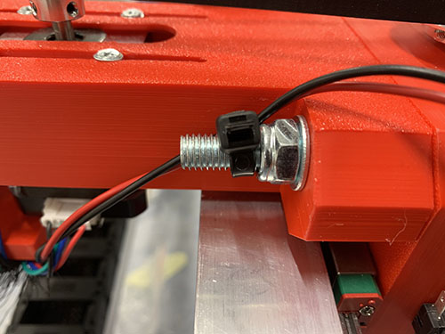
The wires were initially strapped around the lower front bridge beam (seen in the first two images), but as it turned out it blocked the belt tensioner. So they were instead strapped around the M8 tensioner screw, using a cable tie (O11).
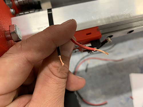
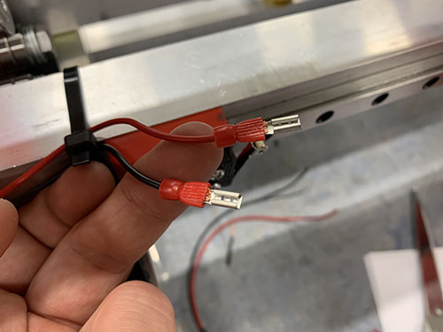
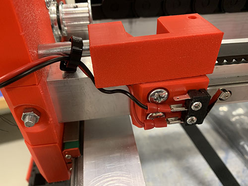
Finally, the open end of the wires were marked using tape and a penn, indicating which end-stop the cables belonged to.
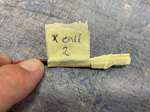
Y-axis (max)
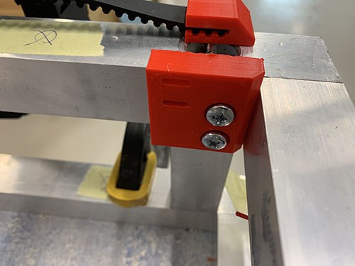
The tall Y-axis end-stop (+) mount (P09) was clamped to the inner side of the upper frame and a sharpie was used to indicate the center of the holes. Note that this end-stop mount can probably be redesigned to gain an extra ~10 mm of Y-axis movement, something I will probably do in the future.
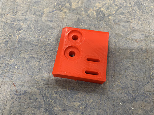
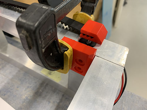
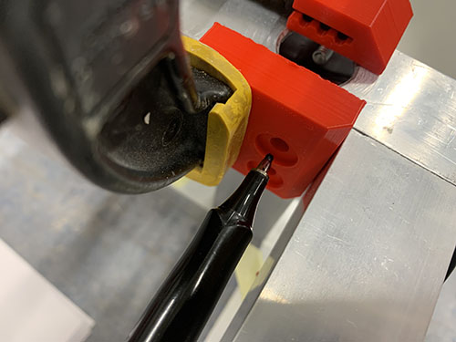
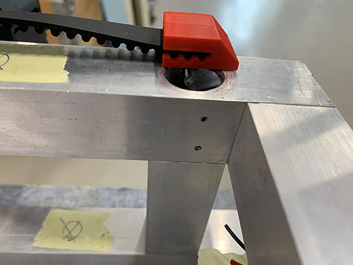
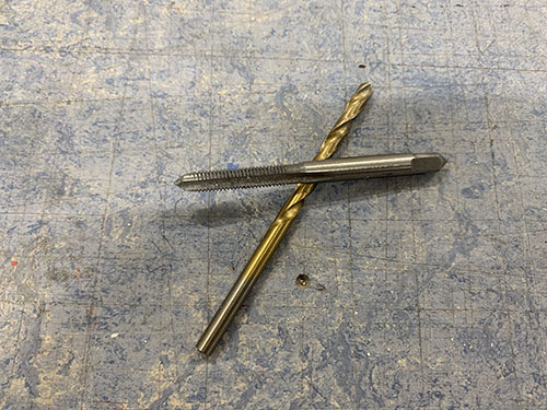
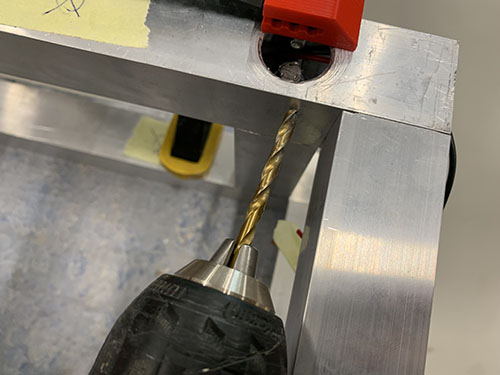
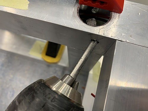
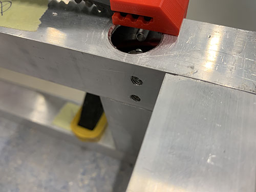
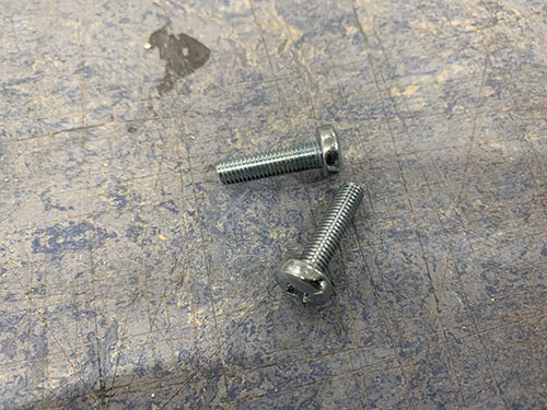
A bradawl and a hammer were then used to make indentations at the center of the holes. Cutting fluid was applied and a 4 mm drill was used to drill the holes, followed by a M5 drill tap. The end-stop mount was then attached to the inside of the upper frame using 2x 20 mm M5 screws (S12).
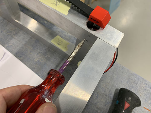
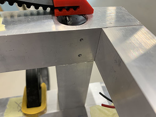
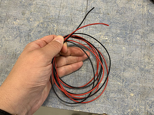
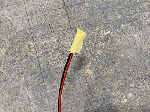
One black and one red 0.75 mm^2 wire (E03) were cut out at a length so that they reached from the Y-axis end-stop (+) and through the 900 mm aluminium profile of the upper frame to the front of the CNC machine.
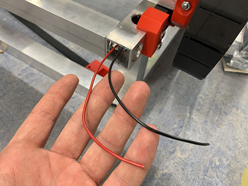
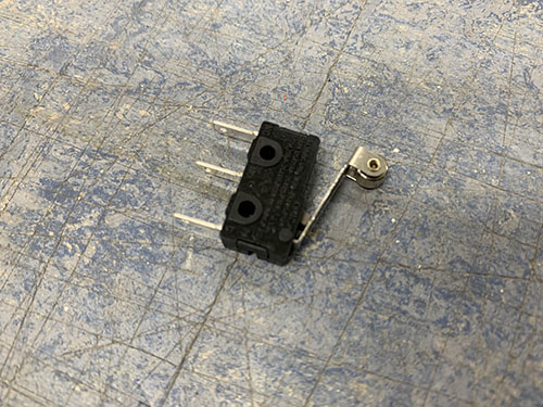
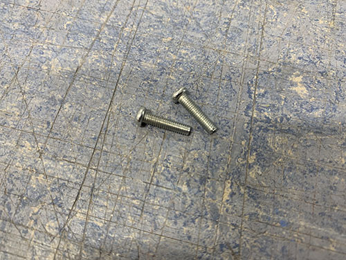
A microswitch (E21) was attached to the tall Y-axis end-stop (+) mount using 2x 12mm M3 screws (S02).
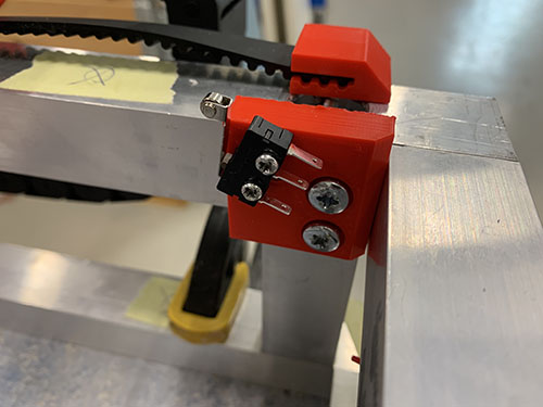
A flexible conduit/hose (O13) was then cut out and the wires were inserted through the conduit. The flexible conduit was then inserted ~50 mm into the 900 mm aluminium profile of the upper frame. The other side was bent around and attached to the outside of the upper frame using cable ties (O11).
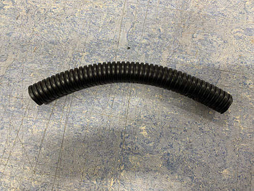
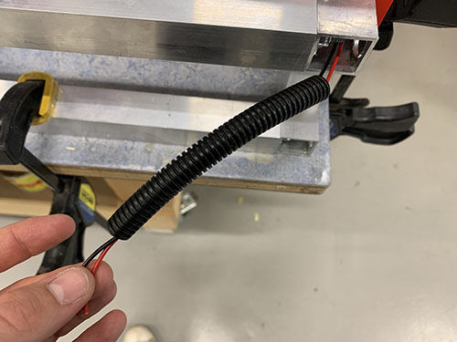
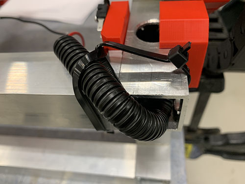
The end of the wires were stripped and twisted. Two 2.8 mm spade connectors (E25) were then attached to the stripped wires using a plier. The red wire was then attached to C (Common terminal) pinout on the end-stop and the black cable was connected to the NO (Normally Open) pinout.
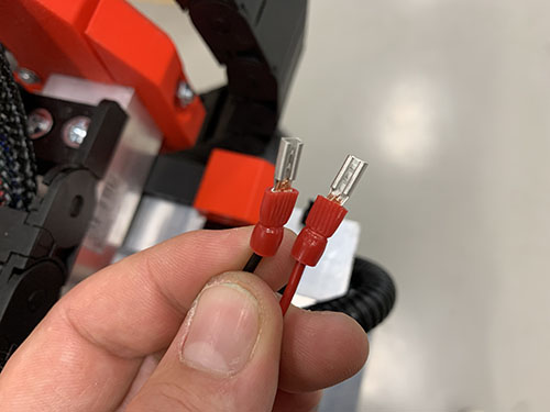
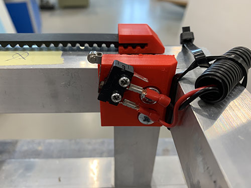
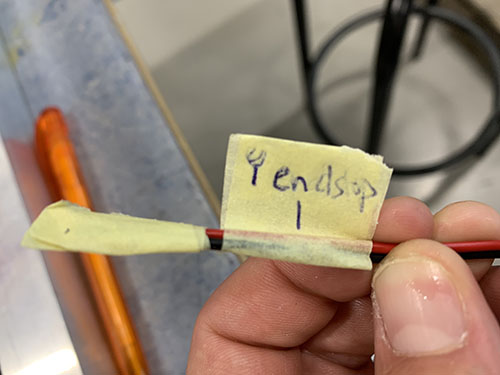
Finally, the open end of the wires were marked using tape and a penn, indicating which end-stop the cables belonged to.
Y-axis (min)
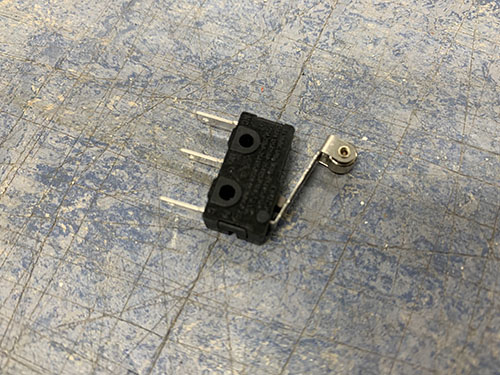
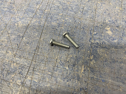
A microswitch (E21) was attached to the Y-axis end-stop (-) mount (P08) using 2x 12mm M3 screws (S02).
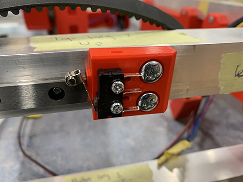
One black and one red 0.75 mm^2 wire (E03) were cut out at a length so that they reached from the Y-axis end-stop (-) and to the front of the CNC machine.
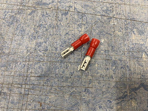
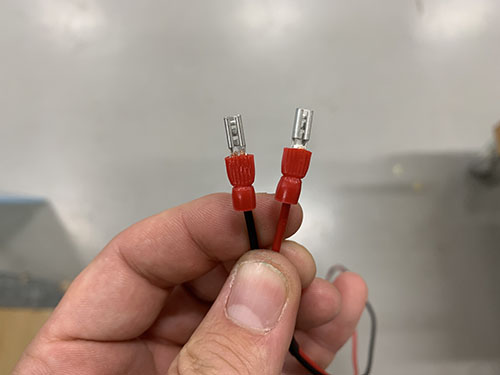
The end of the wires were stripped and twisted. Two 2.8 mm spade connectors (E25) were then attached to the stripped wires using a plier. The red wire were then attached to C (Common terminal) pinout on the end-stop and the black cable was connected to the NO (Normally Open) pinout.

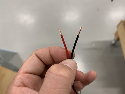
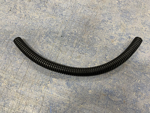
A flexible conduit/hose (O13) was cut out and the wires were inserted through the conduit. The flexible conduit was attached to the outside of the upper frame using cable ties (O11).
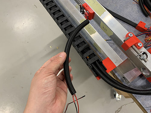
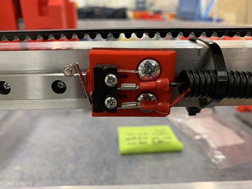
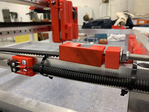
Finally, the open end of the wires were marked using tape and a penn, indicating which end-stop the cables belonged to.
Z-axis (max)
The main purpose of the Z-axis end-stop (+) is, apart from homing the machine, to limit the CNC machine from moving past what the length of the rails allow. As the MGN12H blocks contains a lot of small bearing balls, there's a high risk of them falling out if the blocks move past the rail.
To reduce the complexity and amount of wires, I chose not to include a Z-axis end-stop (-), as you are likely to mill straight through your waste board before there's a risk of moving past the Z-axis min limit. But if you want to add a Z-axis min end-stop, just repeat the process in this section with the new switch flipped around.
First, the vertical carriage slider was moved upwards to its maximum point, where the MGN12H blocks are just about to move past the limit of the rails. The Z-axis end-stop trigger (P39) was then pressed against the outside of the vertical carriage slider and a sharpie was used to mark the center of the holes.
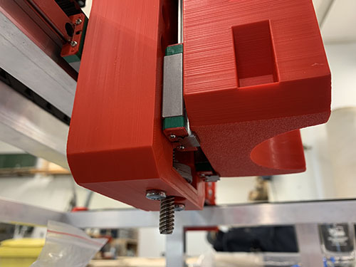
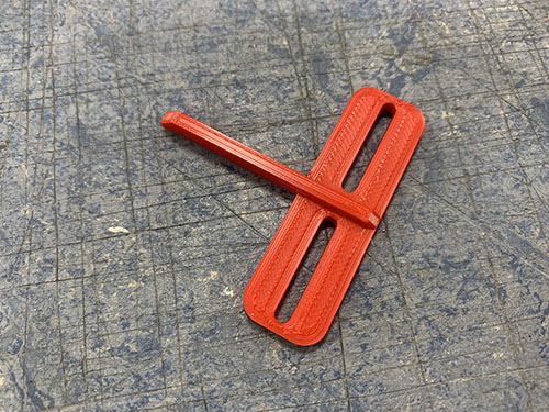
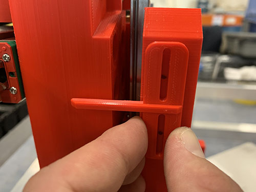
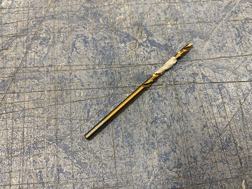
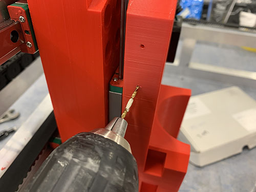
A 2.5 mm drill was used to drill the holes into the vertical carriage slider. A tip is to mark the drill depth needed using tape. The Z-axis end-stop trigger was then attached to the vertical carriage slider using 2x 12 mm M3 screws (S02).
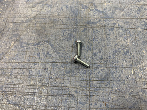
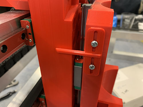
A microswitch (E21) was pressed against the carriage and positioned and aligned to be triggered by the maximum state of the Z-axis end-stop trigger.
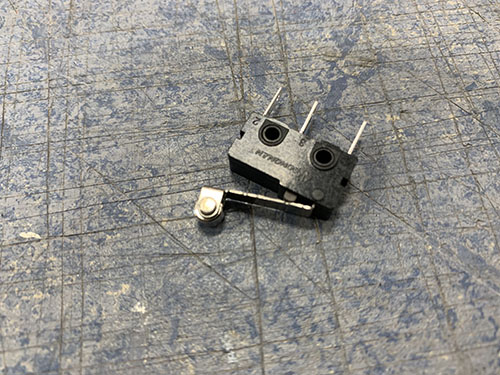
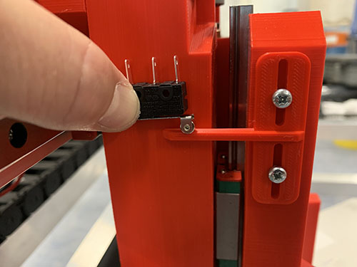
A 2.5 mm drill was used to drill the first hole into the carriage and the microswitch was attached to the carriage using 1x 12 mm M3 screw (S02). After the microswitch was locked into position, the second hole was drilled and the second 12 mm M3 screw (S02) was attached.
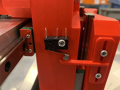
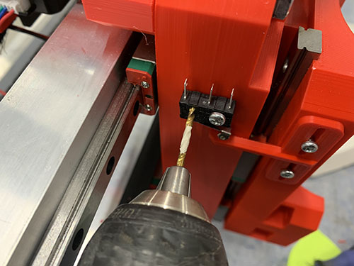
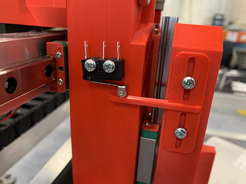
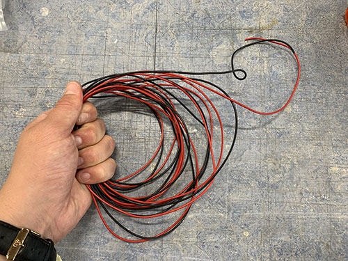
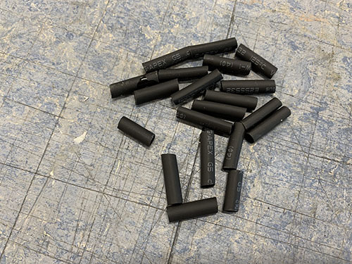
One black and one red 0.75 mm^2 wire (E03) were cut at a length so that they reached over the top bridge beam, through the X-axis cable chain and through the Y-axis cable chain to the front of the CNC machine. A handful of shrinking tubes (O24) were shrunk around the wires to keep them together.
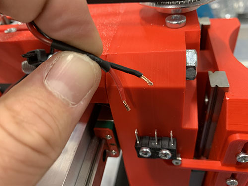
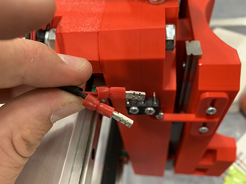
The end of the wires were stripped and twisted. Two 2.8 mm spade connectors (E25) were then attached to the stripped wires using a plier. The red wire was then attached to C (Common terminal) pinout on the end-stop and the black wire was connected to the NO (Normally Open) pinout.
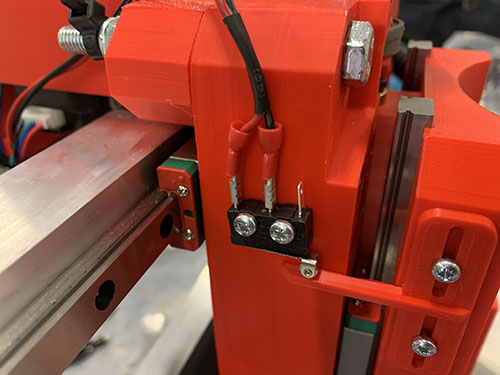
The wires were strapped around the M8 screw keeping the Z motor mount attached to the carriage, using a cable tie (O11).
Finally, the open end of the wires were marked using tape and a penn, indicating which end-stop the cables belonged to.
Stepper motor and end-stop cable management
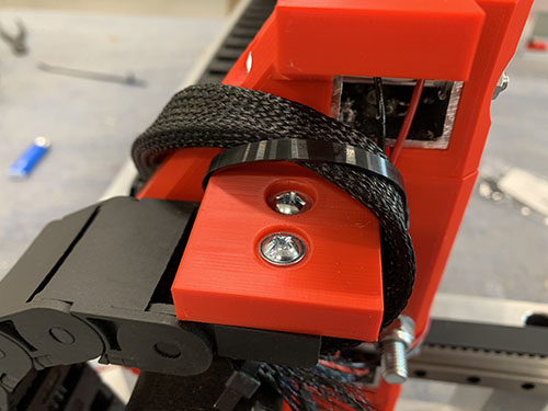
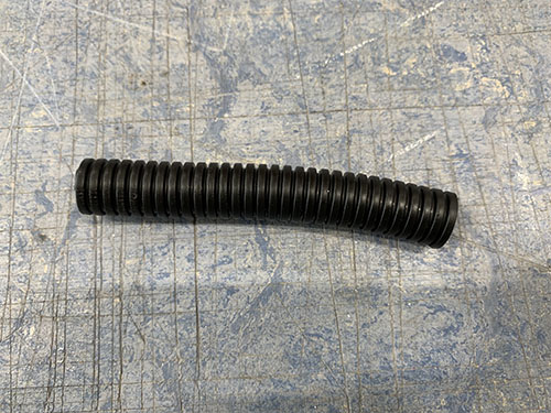
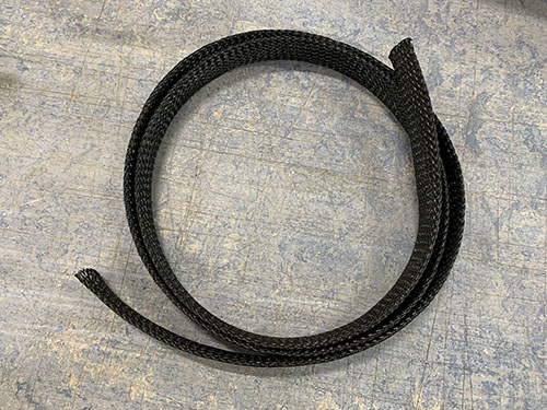
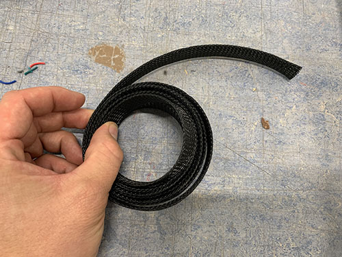
To keep a nice structure of all the wires, braided cable sleeves (O08) and flexible conduits/hoses (O13) were used.
Y-axis steppers and X-axis end-stops
First, the wires from the right-side Y-axis stepper motor were inserted into a small flexible conduit and pushed through the lower bridge beam closest to the carriage.
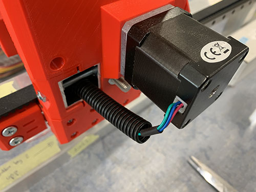
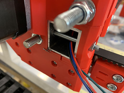
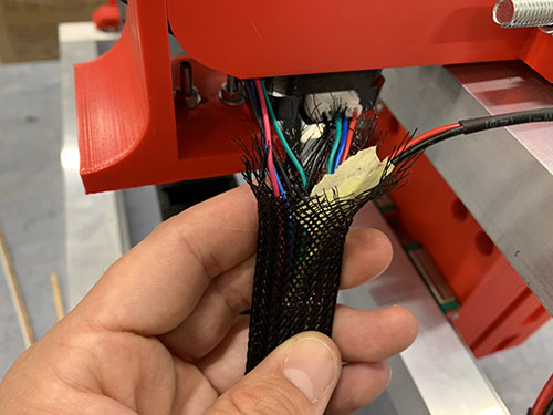
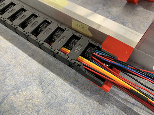
The wires from the two geared Y-axis stepper motors and the two X-axis end-stops were bundled together into the same cable sleeve.
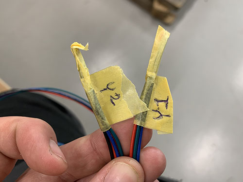
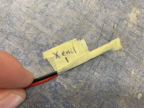
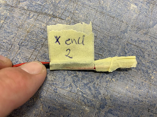
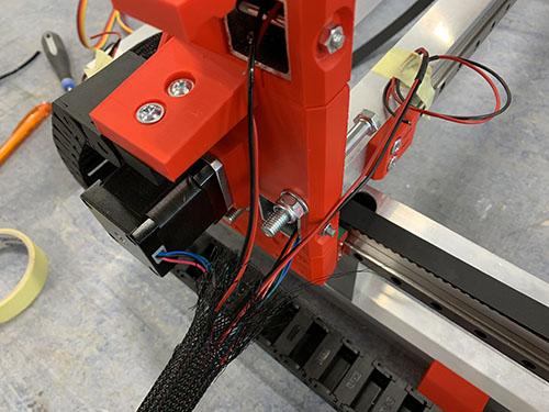
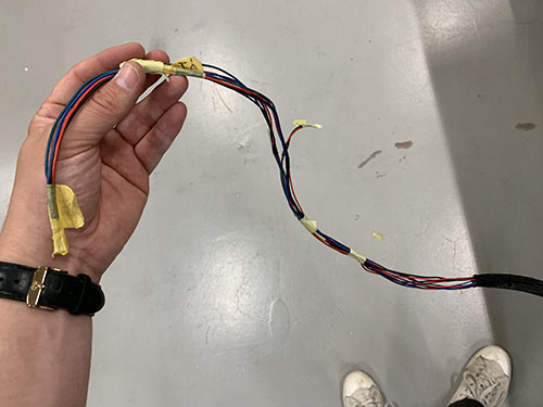
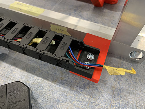
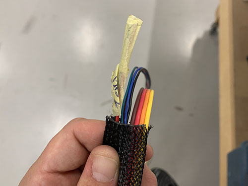
To simplify pushing the wires and the cable sleeve through the cable chain, the wires were taped together, leaving no loose ends to get stuck in the cable chain. This was needed as the wires were longer than the cable sleeve (to reach all the way to the small electronic box in the front of the CNC machine).
A cable tie (O11) was used to close the entrence of the cable sleeve.

X-axis stepper, Z-axis stepper and Z-axis end-stop
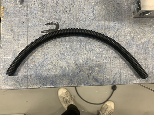
First, the wires from the X-axis stepper motor were inserted into a flexible conduit (O13). The conduit was then bent over the upper bridge beam, strapped to the vaccum mount and Z motor mount, and then pushed behind the Z-axis stepper motor.
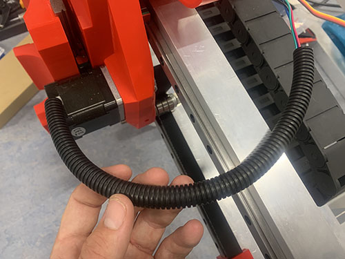
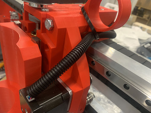
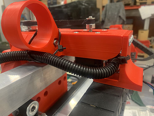
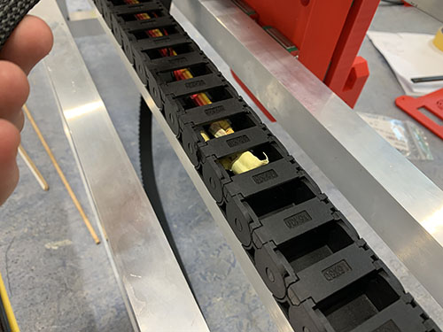
The wires from the X-axis stepper, Z-axis stepper and the Z-axis end-stop were bundled together into the same cable sleeve. The cable sleeve was cut at a length so that it reached through the X-axis cable chain, around the left side-plate and through the Y-axis cable chain.
To simplify pushing the wires through the cable chains, the wires were taped together, leaving no loose ends to get stuck in the cable chains. This was needed as the wires were longer than the cable sleeve (to reach all the way to the small electronic box in the front of the CNC machine).
A cable tie (O11) was used to close the entrence of the cable sock.
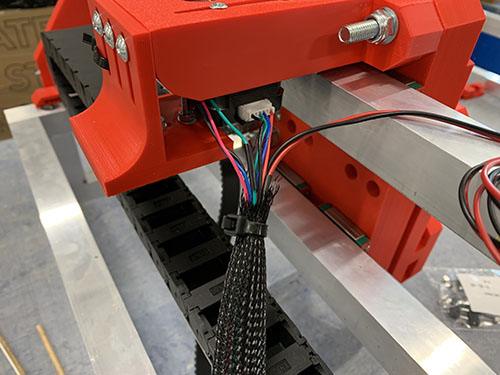
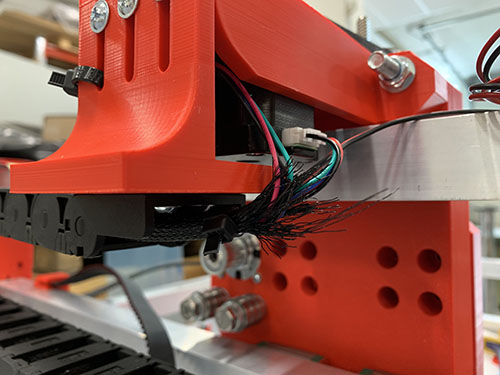

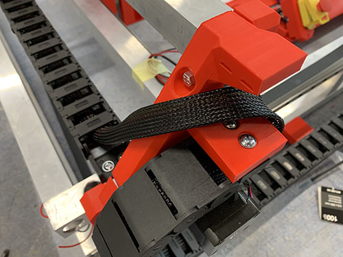
A cable tie (O11) was used to strap the cable sleeve to the left side-plate.