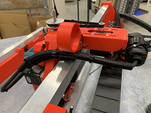
Router
Attach router to carriage
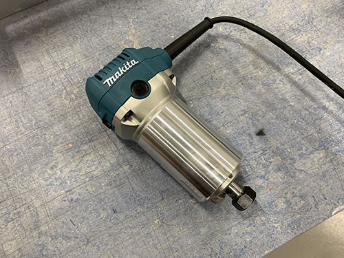
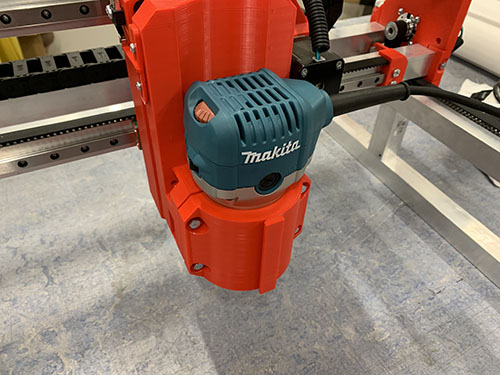
A Makita RT0700CJ (E20) trimming router was used as I was not able to get my hands on the Makita RT0700C that Ivan is using. To my knowledge, the RT0700CJ is just an upgraded European version of the RT0700C, with the same dimensions.
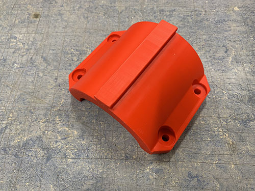
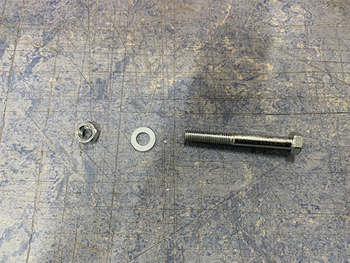
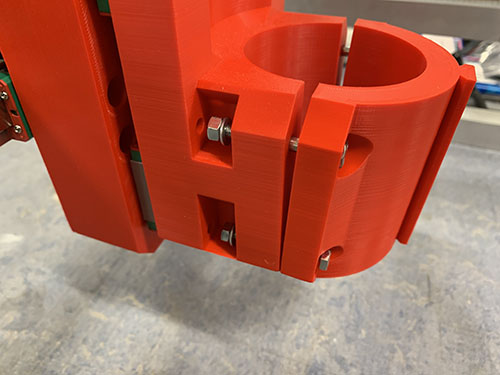
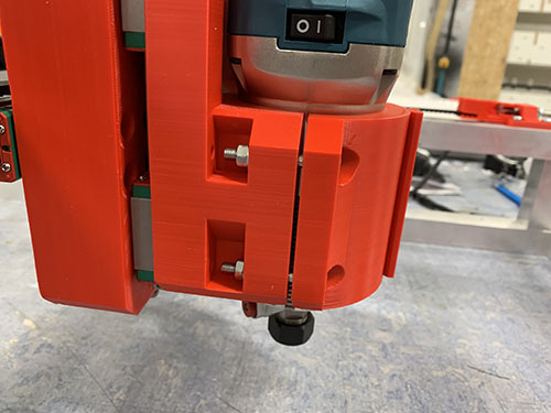
The trimming router was locked in place by using the router bracket (P24), 4x 40mm M5 screws (S13), 4x M5 nuts (N02) and 4x (10mm x 5mm x 1mm) washers (W01).
Router cable management
NOTE: THIS PART INCLUDES WIRING OF HIGH VOLTAGE ELECTRICITY THAT CAN BE LETHAL IF NOT DONE PROPERLY. THE COLORS OF THE CABLES CAN VARY DEPENDING ON REGION/COUNTRY AND YOUR COMPONENTS/PINOUT NUMBERS MIGHT LOOK DIFFERENT. BEFORE YOU CONNECT THE POWER CORD TO THE POWER OUTLET, YOU MUST CONSULT WITH A LICENSED ELECTRICIAN TO MAKE SURE THAT EVERYTHING IS PROPERLY WIRED AND THAT IT IS IN LINE WITH YOUR LOCAL LEGISLATIONS.
To be able to easily replace the trimming router in the future, a power plug (E04) and socket were added (E05).
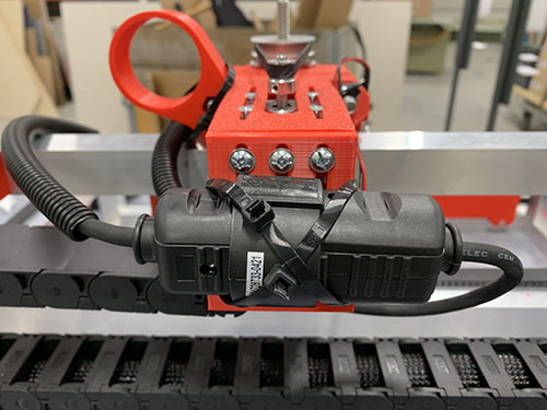
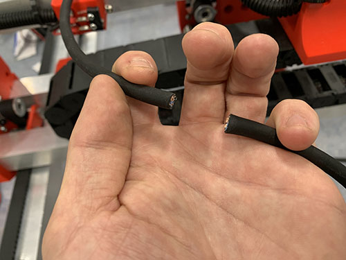
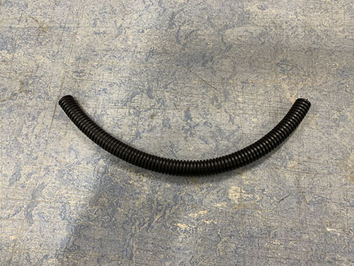
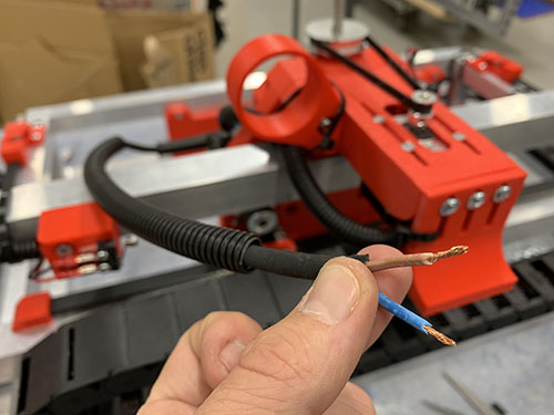
First, the router's power cord was cut and stripped at an appropriate length to reach behind the X-axis cable chain mount. A flexible conduit (O13) was cut out at an appropriate length and the power cord closest to the router was inserted into the conduit. The end of the power cord and the inside wires were then stripped and twisted.
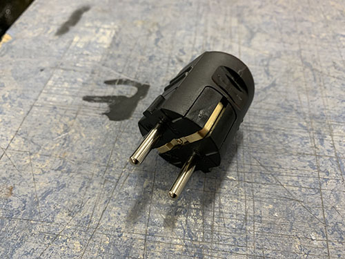
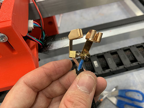
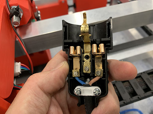
The power plug was opened up and the wires were connected. The built-in strain relief was then tightened around the cable before the plug was closed again.
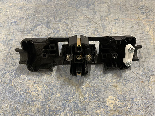
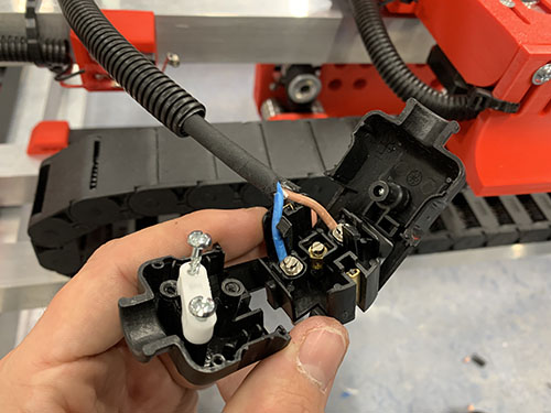
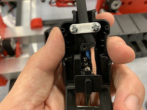
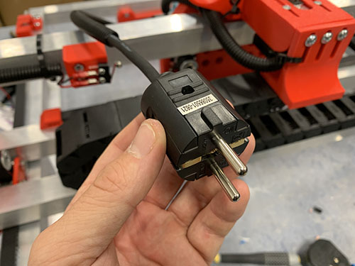
The rest of the power cord was inserted through the Y-axis cable chain, around the left side plate (under the cable tie) and through the X-axis cable chain. Getting the power cord through the X-axis cable chain was quite tricky due to the friction of the rubber cable. A cable tie (O11) was therefore attached to the top of the cable and used to pull the cable through the cable chain.
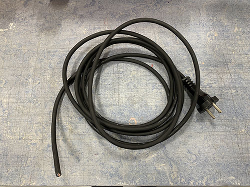
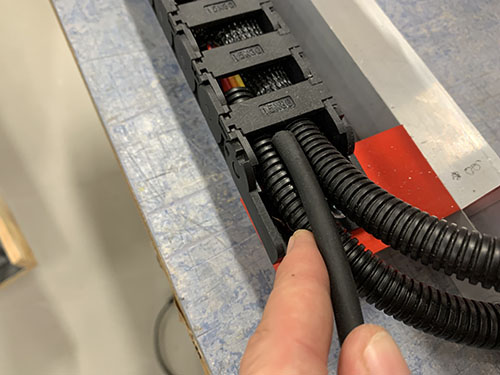
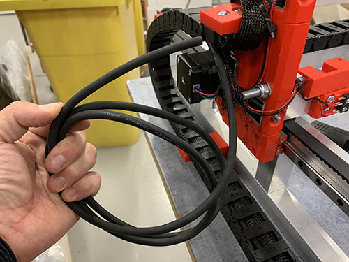
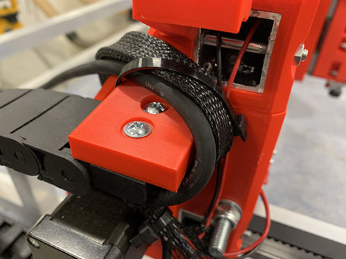
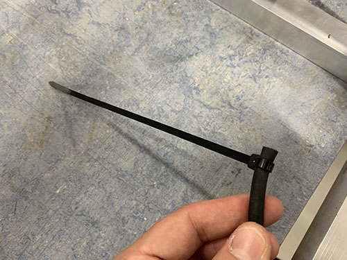
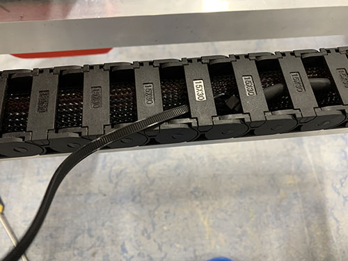
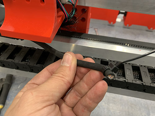
The power cord was pulled through the cable chains and adjusted to an appropriate length to reach behind the X-axis cable chain mount. The end of the cable and the inside wires were then stripped and twisted.
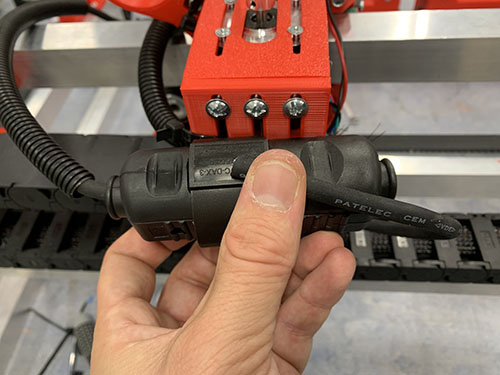

The power socket was opened and the wires were attached to the terminals inside. The built-in strain relief was then tightened around the cable before the socket was closed again.
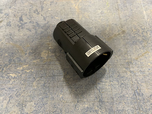
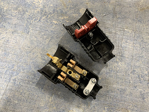
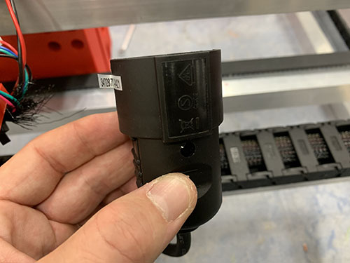
The plug and socket were connected and strapped to the back of the X-axis cable chain mount using cable ties (O11). The flexible conduit with the router power cord inside was strapped to the stepper motor flexible conduit using cable ties (O11). Make sure that it doesn't touch and drag along the upper bridge beam.