Electronic boxes
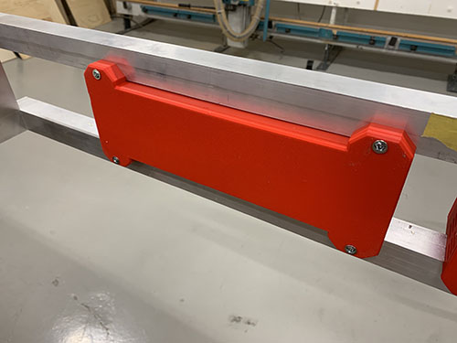
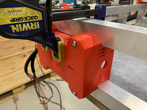
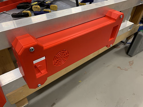
Two electronic boxes were attached to the front side of the CNC machine, a large box to encapsulate the power supply and a small box to encapsulate the Arduino and the CNC shield.
Small electronic box
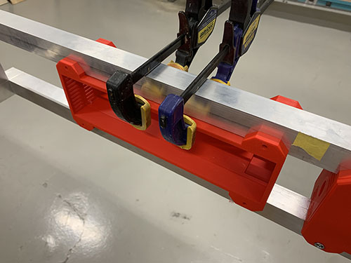
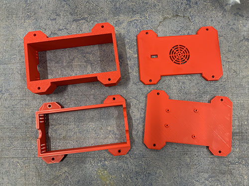
The small electronic box consisted of 4 parts (P02, P04, P13, P15). The two middle parts were clamped together on the front-left side of the frame, closest to the Y-axis cable chain. A finger was used to feel that the two parts were perfectly lined up.
Make sure to have enought space on the left side of the box for the all the stepper motor wires, end-stop wires and router power cable to enter the box (the vertical beam might block if you attach it too far to the left). Also make sure that the two holes are pointing to the left.
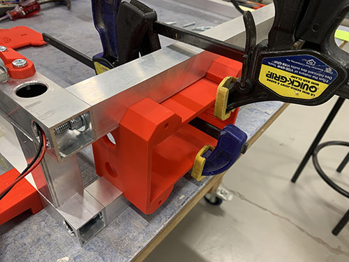
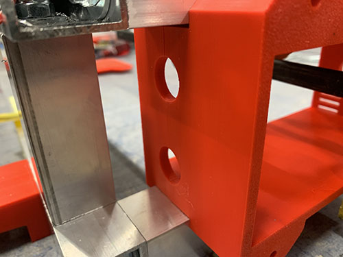
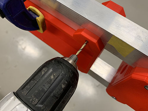
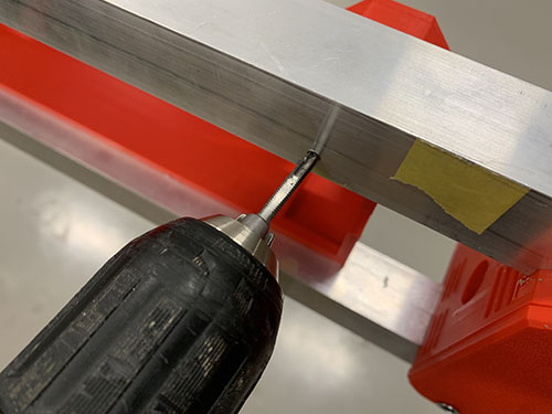
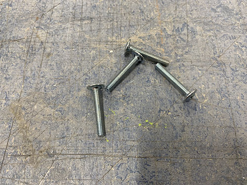
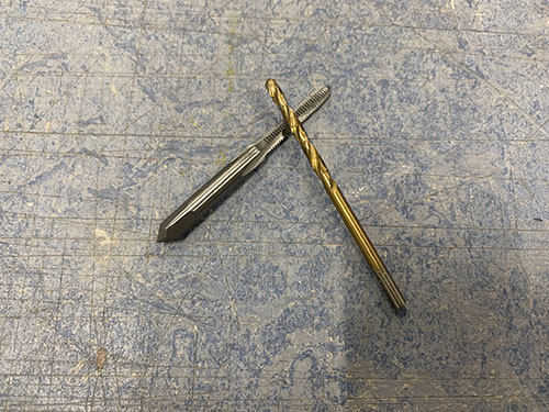
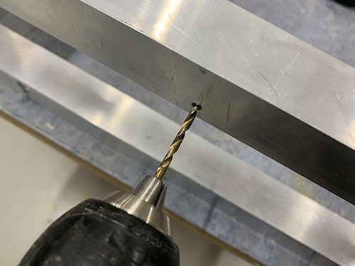
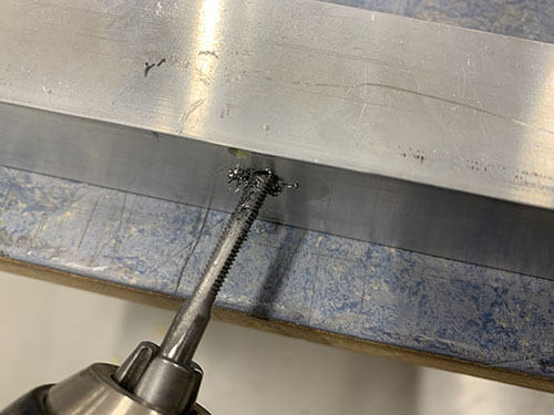
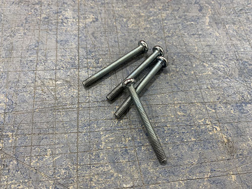
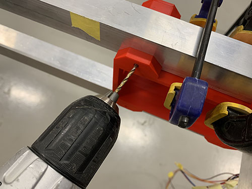
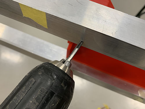
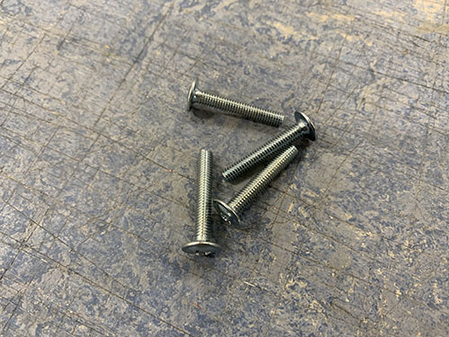
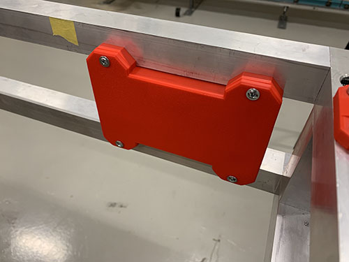
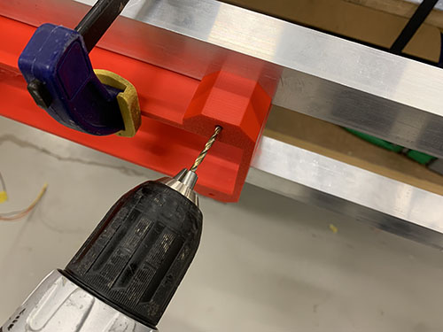
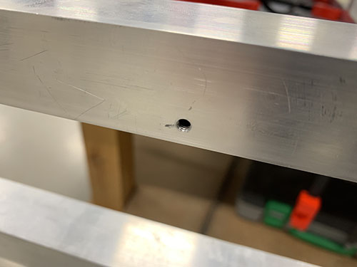
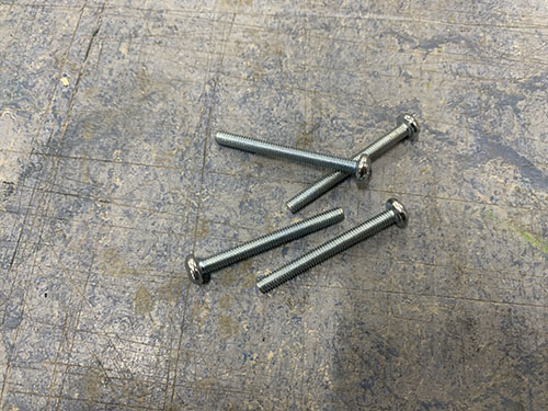
The front-middle part (P13) was attached first. A small 2 mm drill was used to make indentations at the center of the holes. Cutting fluid was applied and a 3 mm drill was used to drill the holes, followed by a M4 drill tap. The front-middle and front part was then attached to the frame using 4x 40mm M4 screws (S11).
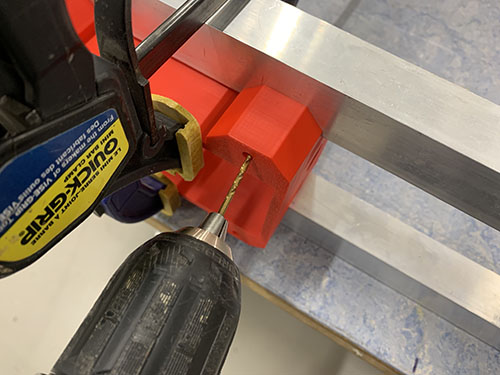
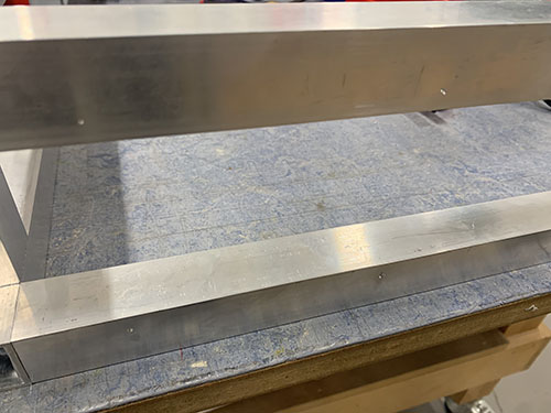

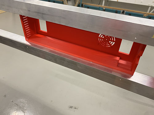
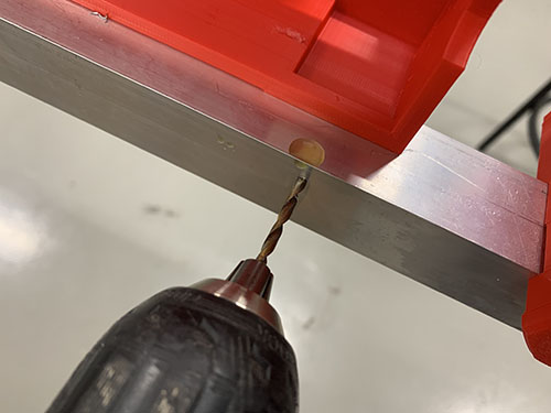
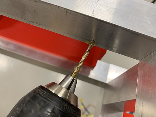
To attach the back-middle part (P02), the whole CNC machine had to be pushed partly over the edge of the working table to be able to drill on the inside of the frame. The machine was firmly clamped to the table.
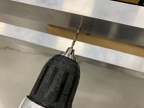
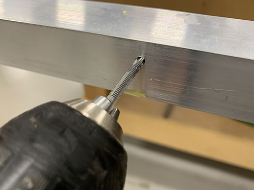
The back-middle part was again clamped to the frame and aligned with the now attached front-middle part. A small 2 mm drill was used to make indentations at the center of the holes. Cutting fluid was applied and a 3 mm drill was used to drill the holes, followed by a M4 drill tap. The back-middle and back part was then attached to the frame using 4x 25mm M4 screws (S10).
Large electronic box
As the small box, the large electronic box consisted of 4 parts (P01, P03, P12, P14). The two middle parts were clamped together to the right of the small box. A finger was used to feel that the two parts were perfectly lined up.
Make sure that the hole is pointing to the left.
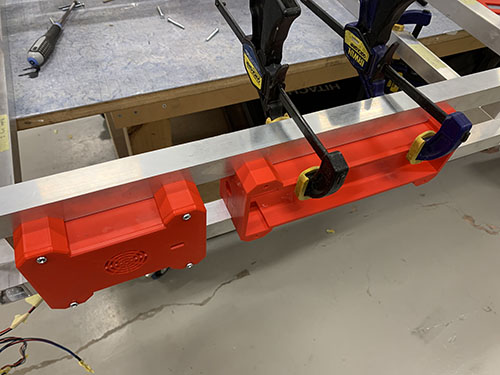
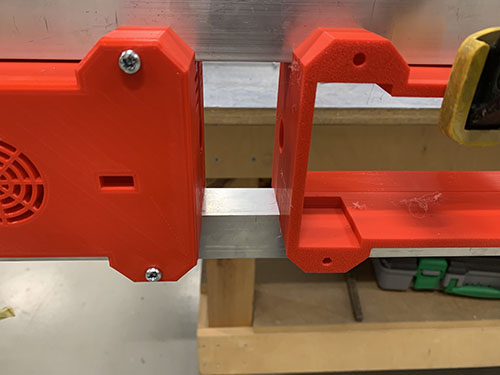
The front-middle part (P12) was attached first. A small 2 mm drill was used to make indentations at the center of the holes. Cutting fluid was applied and a 3 mm drill was used to drill the holes, followed by a M4 drill tap. The front-middle and front part was then attached to the frame using 4x 40mm M4 screws (S11).
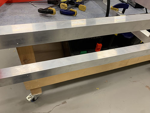
To attach the back-middle part (P01), the whole CNC machine had to be pushed partly over the edge of the working table to be able to drill on the inside of the frame. The machine was firmly clamped to the table.
The back-middle part was again clamped to the frame and aligned with the now attached front-middle part. A small 2 mm drill was used to make indentations at the center of the holes. Cutting fluid was applied and a 3 mm drill was used to drill the holes, followed by a M4 drill tap. The back-middle and back part was then attached to the frame using 4x 25mm M4 screws (S10).