G-Code sender
To be able to send G-Code instructions from the computer to grbl on the Arduino, a G-Code sender is needed. grbl's official list of recommended G-Code senders can be found here: https://github.com/gnea/grbl/wiki/Using-Grbl (Sep 26, 2021)
Install G-Code sender
In this project a G-code sender called Universal G-Code Sender (UGS) was used. The program was downloaded from UGS's official website and the instructions were followed:
https://winder.github.io/ugs_website/download/
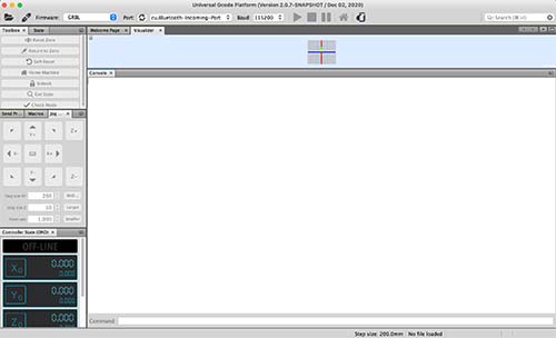
After starting the program, you should see something like this:
Connect G-Code sender to GRBL
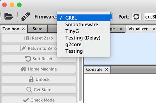
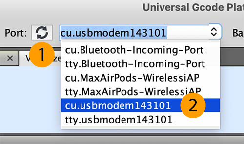
To let UGS know where to connect to, the correct firmware (GRBL) and serial port (cu.usbmodem\
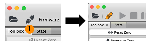
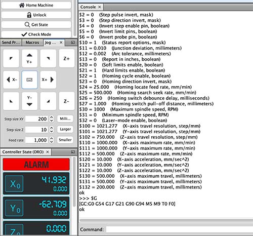
UGS was then connected to the Arduino by clicking on plug/socket icon in the top left corner. If the connection succeeds, you should see the plug/socket icon turn orange and the GRBL configuration outputted in the console.
Adjust GRBL configuration
The GRBL configuration enables you to adjust important settings, such as the maximum mm/min rates for different axes and if the end-stops should be used. A full description of all settings can be found here:
https://github.com/gnea/grbl/blob/master/doc/markdown/settings.md (Sep 26, 2021)
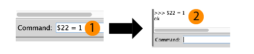
To update a setting, the new setting is inputted into the console command line, e.g.: $21 = 1 to enable end-stops/hard limits. A confirmation that the setting is changed is then outputted in the console.
Enable end-stops/hard limits
The end-stops/hard limits were enabled by updating the following setting:
$21 = 0 -> $21 = 1
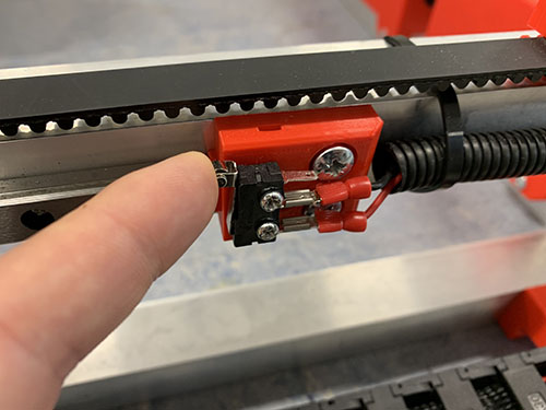
To test that the end-stops were working properly, each end-stop was tested by manually triggering it with a finger. After triggering, an alarm should be raised in UGS.
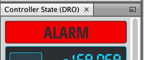
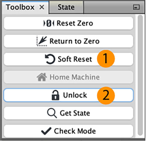
After the alarm was triggered, UGS was reset by clicking Soft reset and Unlock.
Calculate and set travel resolutions
The most important settings to adjust is the X-axis, Y-axis and Z-axis travel resolutions. These settings tells GRBL how many steps it should take to move one millimeter. The travel resolution depends on the stepper motor's steps per revolution, the microstepping, the teeth spacing and the number of teeth on the timing pulley(s).
The following equation was used to calculate the travel resolution (steps/mm) for each stepper:

In this project, this is how the travel resolutions were calculated:
| Stepper motor | Microstepping | Step angle | Steps per revolution | Teeth spacing | Number of teeth - Pulley 1 | Number of teeth - Pulley 2 | Travel resolution |
|---|---|---|---|---|---|---|---|
| X-axis | 16 | 0.094 deg | 360/0.094 = 3829.7872 steps | 5 mm (HTD5M) | 12 | 1 (used when no pulley 2) | (16*3829.7872)/(5*12/1) = 1021.277 |
| Y-axis (1) | 16 | 0.094 deg | 360/0.094 = 3829.7872 steps | 5 mm (HTD5M) | 12 | 1 (used when no pulley 2) | (16*3829.7872)/(5*12/1) = 1021.277 |
| Y-axis (2) | 16 | 0.094 deg | 360/0.094 = 3829.7872 steps | 5 mm (HTD5M) | 12 | 1 (used when no pulley 2) | (16*3829.7872)/(5*12/1) = 1021.277 |
| Z-axis | 16 | 1.8 deg | 360/1.8 = 200 steps | 8 mm (acme rod) | 16 | 60 | (16*200)/(8*16/60) = 1500 |
The travel resolutions were updated:
- X-axis travel resolution:
$100=250.000->$100 = 1021.277 - Y-axis travel resolution:
$101=250.000->$101 = 1021.277 - Z-axis travel resolution:
$102=250.000->$102 = 1500.000
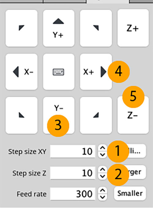
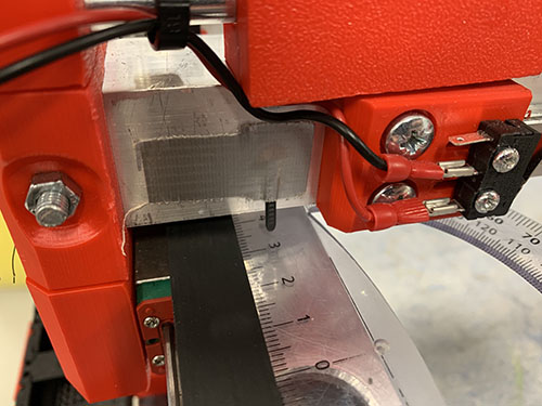
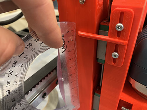
The calculated travel resolutions were validated by moving each axis 10 mm in UGS and measuring the actual distance moved.
Other configurations
The homing cycle is when the CNC machine automatically moves all axises to it's limits to home itself before starting the job. I disabled this as I will manually jog the router to it's position:
$22 = 1 -> $22 = 0
The X-axis and Y-axis minimum rates were increased to 1000:
- X-axis maximum rate:
$110=500.000->$110 = 1000.000 - Y-axis maximum rate:
$111=500.000->$111 = 1000.000
The X-axis and Y-axis maximum travel were increased to 500:
- X-axis maximum travel:
$130=200.000->$130 = 500.000 - Y-axis maximum travel:
$131=200.000->$131 = 500.000