Y-axis
Side plates to upper frame
Before attaching the side plates, the MGN12H blocks (O22) were added back onto the rails, 2x on each side. Be careful when sliding them onto the rails, there are multiple small bearing balls that easily fall out of the blocks.
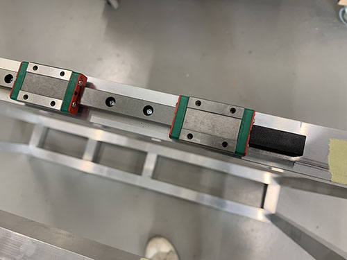
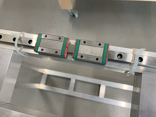
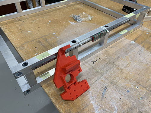
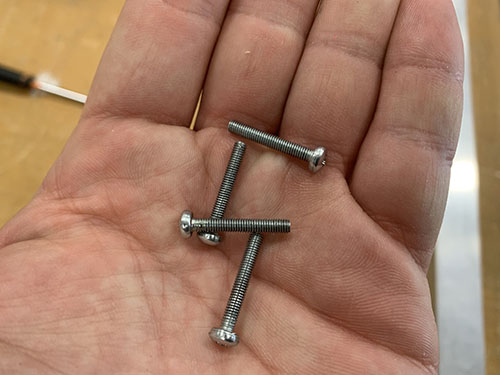
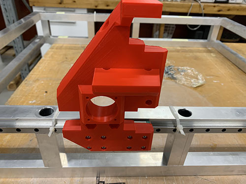
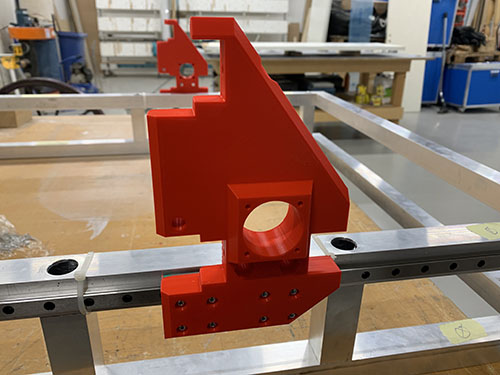
The left (P20) and right (P29) side plates where then attached to the blocks using 16x 20 mm M3 screws (S04) (8x on each side plate). Make sure to attach the plates on the correct side (see images below).
I had to redesign the left side plate and reprint it later in the build (after the images were taken). Therefore, the left side plate seen in the upcoming images look a bit different than the one used (see next image for the left side plate used).
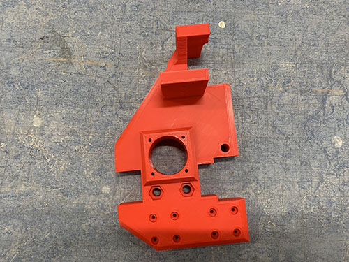
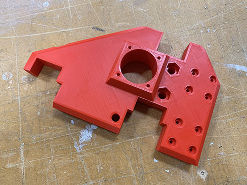
Y-axis motors, idlers and pulleys to side plates
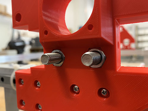
Each idler were made up out of 1x idler blocker (P16), 2x 60 mm fully threaded M8 screws (S15), 6x 698zz bearings (O01) and 8x (15 mm x 8.5 mm x 1.5mm) washers (W03) (2x closest to the idler blocker and 6x closest to the side plate). The idlers were then attached to each side plate using two M8 nuts (N03). Make sure that the bearings are spinning freely.
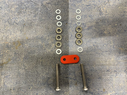
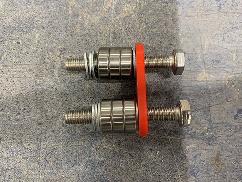
As I designed and added the idler blocker later on in the build, some of the images doesn't have it and they also have 3x washers instead of 1x washer closest to the screw head. I left these images anyways in the guide so you can see how it looks when you attach the idlers, but please ignore the wrong number of washers. Also ignore all the other things around the idlers in the upcoming 2 images, they are taken later on in the build.
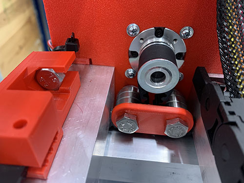
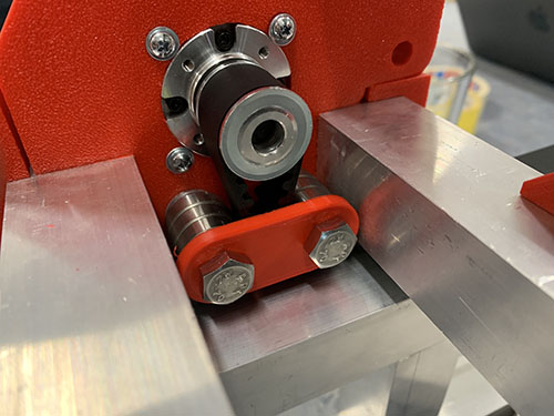
Should be idler blockers and a different number of washers in the upcoming images.
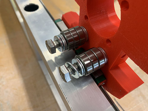
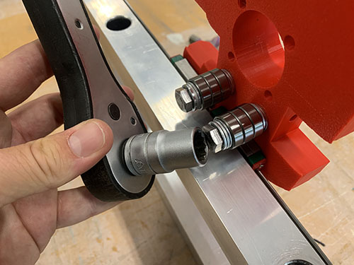
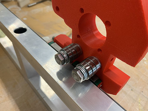
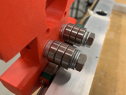
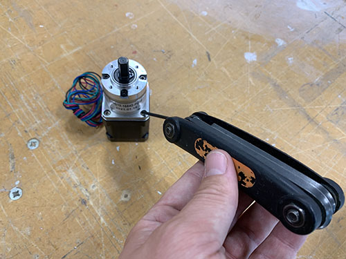
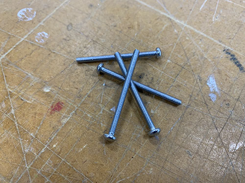
To attach the stepper motors to the side plates, the 4x M3 screws (S07) locking the gear box to the motor were removed. Save these as they will be used later on to attach the power supply and Arduino to the electronic boxes.
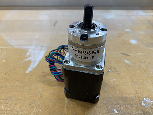
The 2x geared stepper motors (E18) were then inserted into the large holes on the side plates, facing inwards. 4x 40 mm M3 screws (S06) and 4x M3 washers (W05) were used to lock each stepper motor to the side plates (I forgot to add the washers in the images below, therefore they're not visible). The motors should be attached so that the cables are facing in the direction of the two bridge beams (i.e. the longer vertical surface on the side plates).
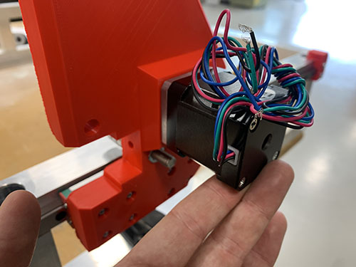
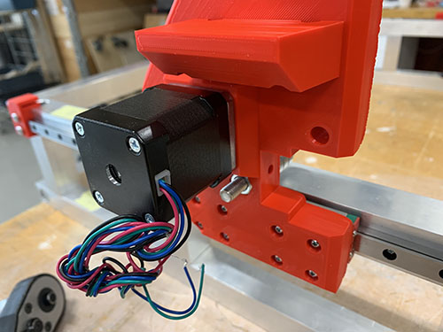
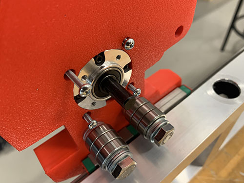
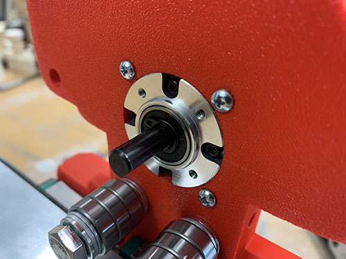
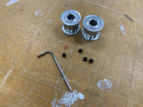
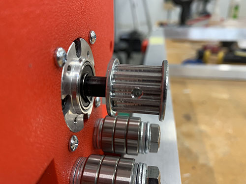
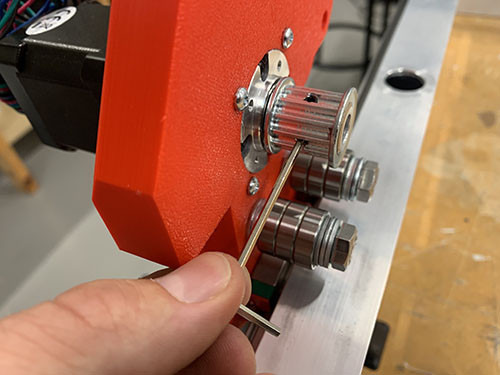
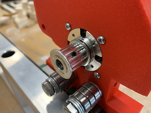
1x HTD5M timing pulley (O18) was attached to each motor shaft using set screws.
Y-axis belt tensioners and end-stop mounts
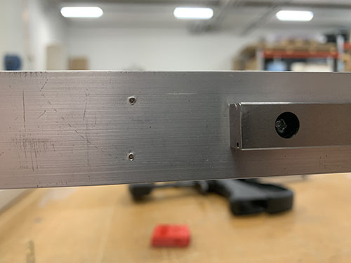
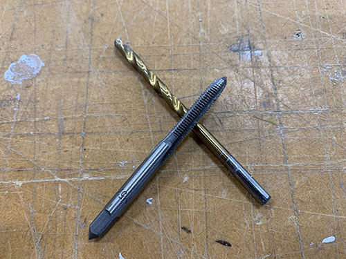
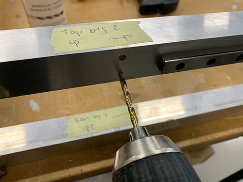
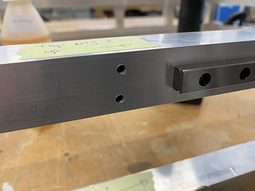
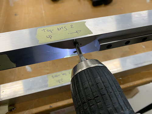
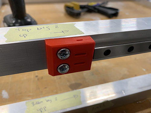
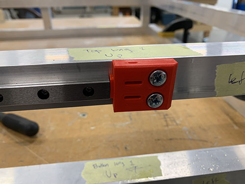
2x fixed belt tensioners (P19, P28) were attached to the longer aluminium profiles of the upper frame using 4x 20mm M5 screws (S12) (2x for each fixed belt tensioner). When aligning the fixed belt tensioners, make sure that the "belt opening" is pointing in the direction of the rails (1x fixed belt tensioner for each rail). Also make sure that the fixed belt tensioners are positioned on the correct side of the rail (see images). Similar to before, a bradawl and a hammer were used to make indentations at the center of the holes. Cutting fluid was applied and a 4 mm drill was used to drill the holes, followed by a M5 drill tap.
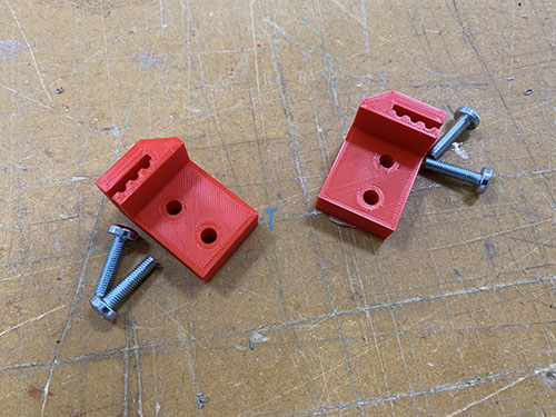
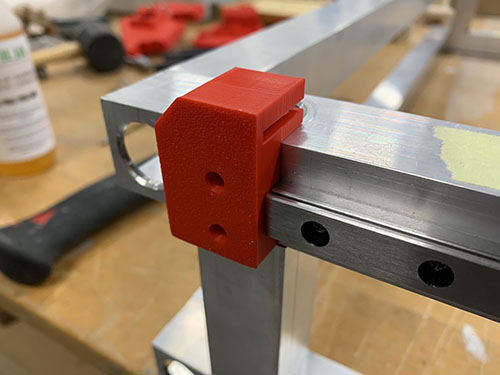
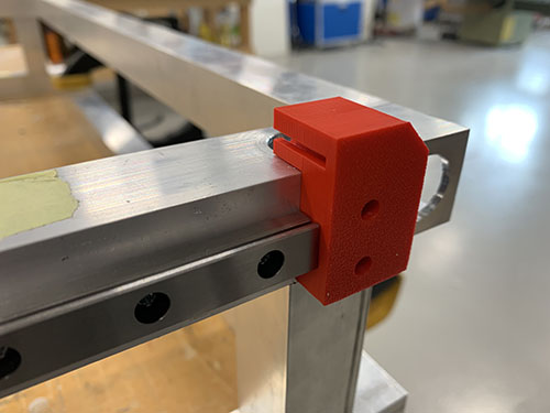
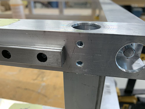
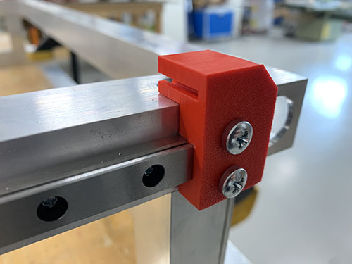
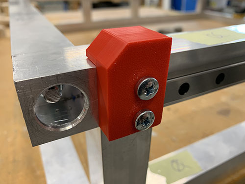
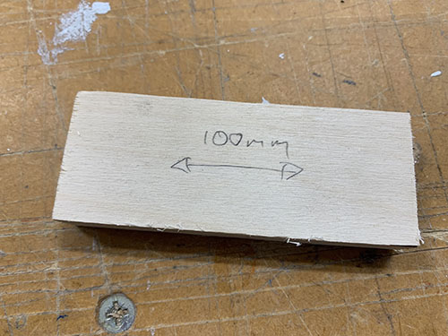
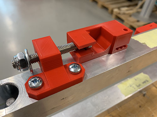
2x belt tension sliders (P17, P26) were attached on the opposite side of the fixed belt tensioners, ontop of the aluminium profile, using 4x 20mm M5 screws (S12). To get them aligned at the exact same place on both sides, a 100 mm distance was cut out and a flat support was clamped to the inner side of the profile. The same drill and tap size were used as for the fixed belt tensioners (4mm drill, M5 drill tap). Make sure that the belt tension sliders are pointing outwards.
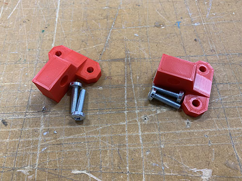
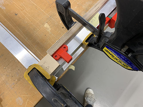
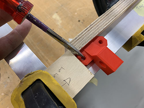
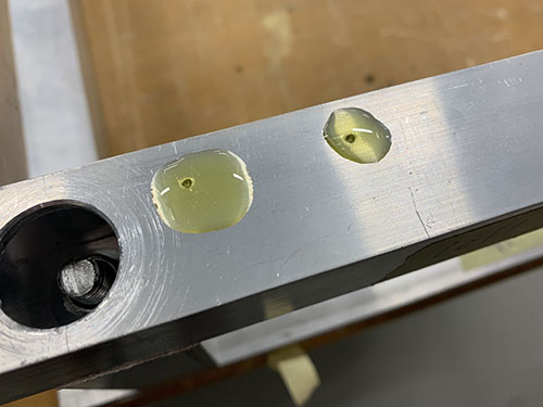
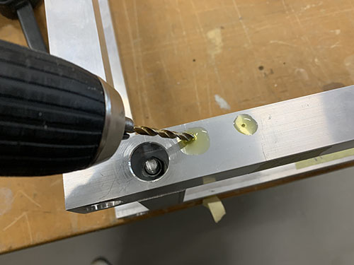
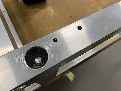
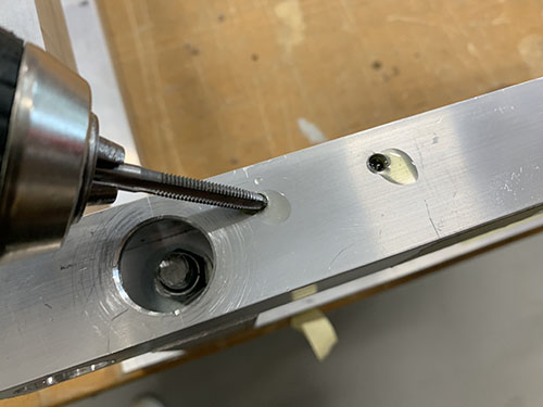
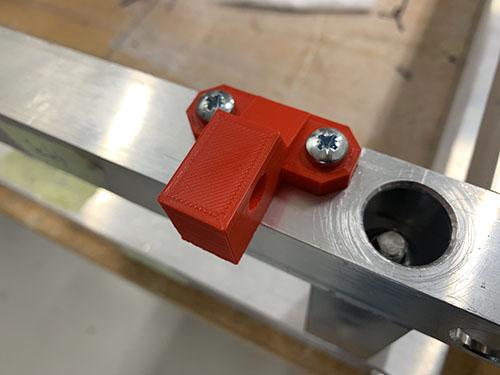
2x end-stop mounts (P08) were then attached to the same side as the belt tension sliders using 4x 20mm M5 screws (S12), facing outwards and aligned with the rails. The same drill and tap size were used as for the fixed belt tensioners (4mm drill, M5 drill tap).
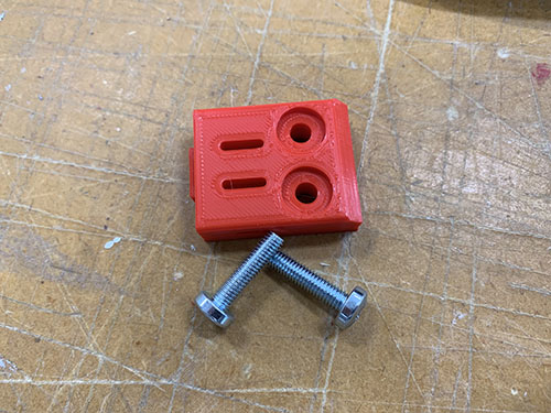
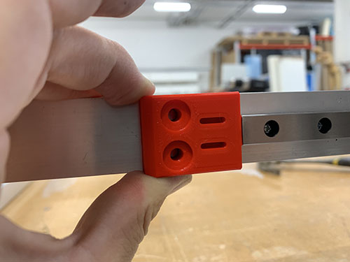
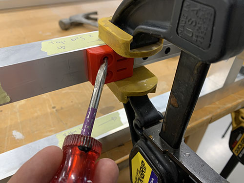
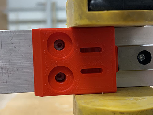
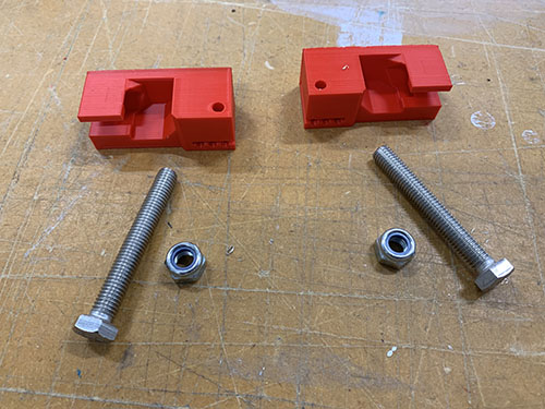
The belt tensioners (P18, P27) were loosely attached to the belt tension sliders using 2x 60 mm fully threaded M8 screws (S15), 2x M8 nuts(N03) and 2x (20mm x 10mm x 2mm) washers (W04).
Y-axis HTD5M belts
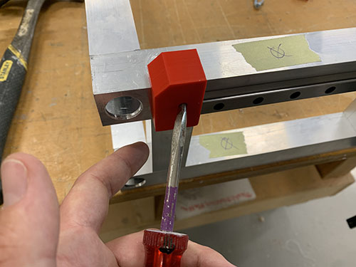
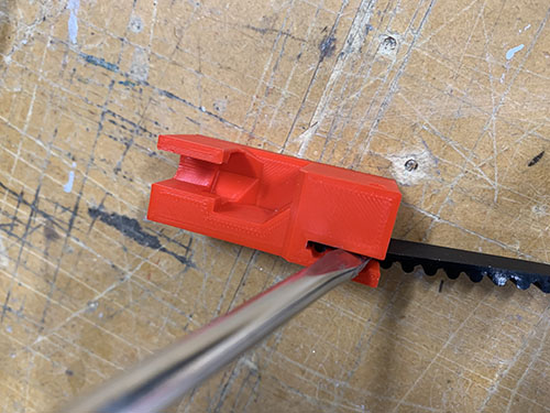
The HTD5M belt (O17) was first inserted into one of the fixed belt tensioners using a flat screw driver. It was then stretched along the aluminium profile, below the first idler, around the timing pulley, below the second idler and all the way to the belt tensioner.
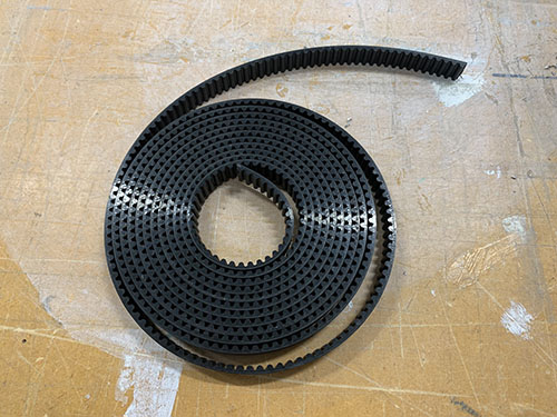
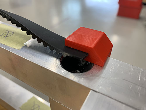
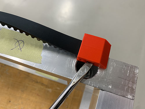
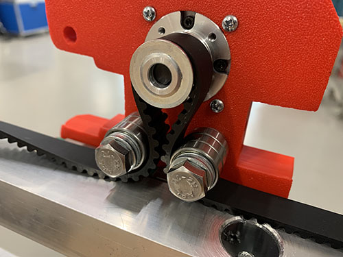
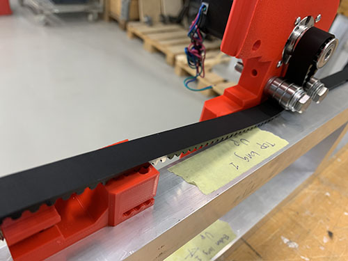
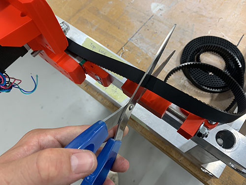
A scissor was used to cut the belt at an appropriate length. The loose end was then inserted into the belt tensioner using a flat screw driver and the belt was stretched by tightning the M8 nut.
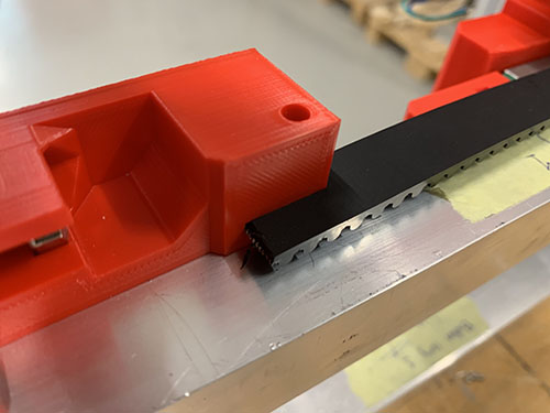
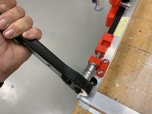
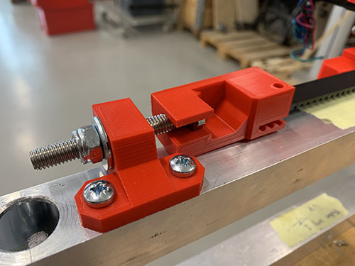
Make sure that the belt is not too loose and not too tight.
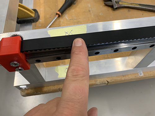
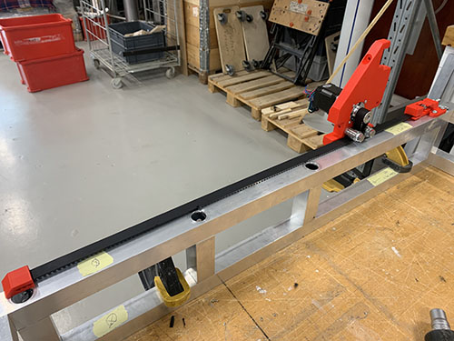
Repeat on the other side.